Table of Contents
Advertisement
Quick Links
Advertisement
Table of Contents

Related Manuals for IFC IFC-BOXi5-10210

Summary of Contents for IFC IFC-BOXi5-10210
- Page 1 IFC-BOXi5-10210 (User Manual) Low power fanless mini PC...
- Page 2 Warning IFC industrial PC products are only allowed to be used for the specified conditions of the catalogue and related technical documents. If you want to use other company's products and components, you must get the recommendation and permission from IFC Technology.
- Page 3 Disclaimer IFC Technology reserves the right to change this manual and the products are subject to change without prior notice. We are not responsible for any direct, indirect, intentional or accidental damage or hidden dangers caused by improper installation or use.
-
Page 4: Table Of Contents
Catalogue 1. Product Introduction ..................... 5 1.1 Product overview ..................5 1.2 product specification (Main parameter) ............5 2. Application Planning ...................... 6 2.1 Transportation ....................6 2.2 Storage ......................7 2.3 Open and inspection of delivered equipment ..........7 2.4 Installation .................... -
Page 5: Product Introduction
1. Product Introduction 1.1 Product overview IFC-BOXi5-10210 is an ultra low power fanless mini PC. It uses Intel® core I5 8260U quad core i3 10110U and I5 10210, i7-10710U processors, support Windows 8/10/11 & Linux OS etc., support 1*M.2 2280 and 1*2.5 inch HDD and very convenient to use. -
Page 6: Application Planning
2. Application Planning 2.1 Transportation Well packaged products can by any means of transport, to any place, in the long-distance transportation shall not be installed in the open cabin and carriages, midway transshipment shall not be stored in open-air warehouse, not allowed to be transported with inflammable, explosive, corrosive goods together. -
Page 7: Installation
● Verify that the shipment contains the complete equipment and accessories that you ordered separately. If there is any discrepancy or exist shipping damage, please contact customer service. 2.4 Installation ■Desktop ■VESA □19 inch Rack Mount □Embedded □Portable 3. Device Connection 3.1 Precautions before device connection Warning Connected or built-in peripherals shall not be connected to devices of opposite polarity. -
Page 8: Connect The Device To The Power Supply
3.2 Connect the device to the power supply Steps of connect the device to Diagrammatic drawing the power supply Connect 9-36 VDC power adapter to the power input port ①, then press the front panel power switch button, PC start with blue power LED on ①... -
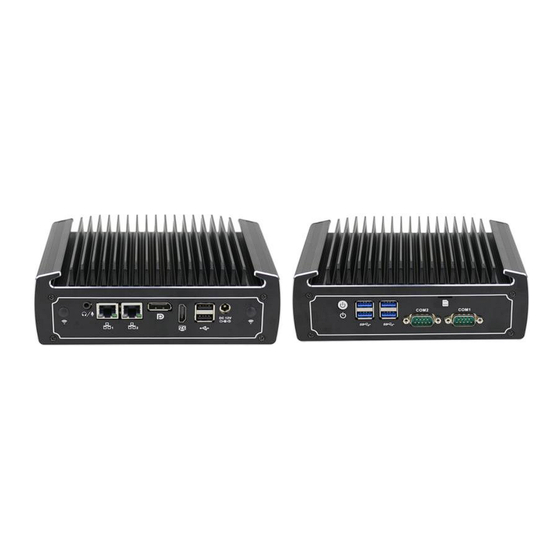
Page 9: I/O Port
4.3 I/O Port Back Plate Port Name Audio/Mic 2*LAN HDMI 2*USB2.0 1*DC-IN 12V WiFi holes Support Synchronous Remark and Asynchronous Dual Display... -
Page 10: Internal Expansion Port
Front Plate Port Name Switch botton 4*USB3.0 2*COM SIM card slot Remark No COM is Optional 4.4 Internal expansion port Internal expansion port Port Name Notebook Memory Slot M.2 2280 Mini PCIE (WIFI/3G/4G Optional) WIFI hole... -
Page 11: Status Indicator Led
4.5 Status indicator LED Name Description Meaning Not Light Power off POWER PC boot up Light Running 4.6 Install the internal parts Remove four M2.5*6 screws from the bottom plate (see below), remove the bottom plate,then please install the RAM, WIFI module, M.2 or 2.5” HDD and other accessories. -
Page 12: Mainboard
Warning This operation is only suitable for customers who purchase N15 barebone PC. Customers who have installed internal accessories should not disassemble the machine at will. 4.7 Mainboard... -
Page 13: Definition Of Pins
4.8 Definition of Pins Note: The identification method of the first pin of the first pin in the pins on the motherboard is: 1. There is a white bold silk screen mark or an arrow mark; 2. The pins seen on the back of the motherboard are square holes. Signal Signal HDD LED +... - Page 14 COM1/COM2 definition Signal Signal COM DB9 definition RS232 RS485 COM1/COM2 RS232/RS485 Jump cap definition (need to cooperate with BIOS settings to take effect)
- Page 15 COM port LE1/LE2/LE3 Mode RS232 COM1 RS485 RS232 COM2 RS485 SATA1 Signal SATA TXP SATA TXN SATA RXP SATA RXN JSATA Signal +12V...
- Page 16 JPWR1 Signal AUTO-ON CPU_FAN1 Signal VCC +12V FG(speed signal) GPIO1 Signal Signal + V5 +V3.3 GPIO 56 GPIO 57 GPIO 60 Warning The internal wiring of the PC has been installed, and the wire plug and screw have been fixed with glue. Please do not disassemble and install the motherboard, jumpers and other operations at will to avoid damage to the motherboard.
-
Page 17: Bios Setting
5. BIOS Setting BIOS settings menu is divided into the following options: After the device starts, press the "Delete" button to enter the BOIS setting interface. Main: BIOS information, time and date Advanced: BIOS advanced menu settings Chipset: chipset settings Security: security settings Boot: Boot option settings Save &... - Page 18 1. Setting the function of auto power on when there is electricity “Advanced”→“System power Management” → “Restore On AC Power Loss”, See picture as follow Restore on AC Power loss function description: Power Off: After the device is connected to the 12V power supply, you need to press the power button to turn it on;...
- Page 19 2. Setting timing boot function Choose “Advanced”——“System Power Management”——“Wake System From RTC Alarm”——“Fixed Time”, then set the time of booting up every day, then press “F4”——“YES” then exit. Wake System From RTC Alarm function description: Alarm Date: The unit date of the wake-up time, when it is set to 0, it means every day; Alarm Hour: The wake-up time unit is hours;...
- Page 20 3. COM port configuration “Advanced” →“ITE Super IO Configuration”→“Serial Port 1 Configuration” Serial Port Configuration function description: serial Port: Enabled enable COM port; serial Port: Disabled to close the COM port; Communication Protocol: RS232 and RS485 two modes can be selected (need to cooperate with the motherboard jumper cap settings to take effect).
- Page 21 4. BOOT boot configuration Boot Configuration function description: Setup Prompt Timeout: the waiting time for the boot logo, the time unit is seconds; Bootup NumLock State: The state of the NumLock key on the keyboard at startup; Quiet Boot: "Enabled" turns on the boot logo, and "Disabled" turns off the boot logo. Warning Please do not change the BIOS setting at will to avoid the PC can’t work.
-
Page 22: Daily Maintenance
6. Daily maintenance When the PC is in normal use, please ensure that the PC is working in a non-vibration environment to avoid damaging the hard disk and internal accessories. When using the PC, please pay attention that the environmental temperature should between -10℃... - Page 23 7. Troubleshooting for Common hardware failure fault phenomenon analysis of causes repair method Suggest to plug tighten the The power The PC doesn’t power cord or change the adapter is work boot up after socket; or not press the power Change the power adapter;...
Need help?
Do you have a question about the IFC-BOXi5-10210 and is the answer not in the manual?
Questions and answers