
Related Manuals for Haug Multistat S

Summary of Contents for Haug Multistat S
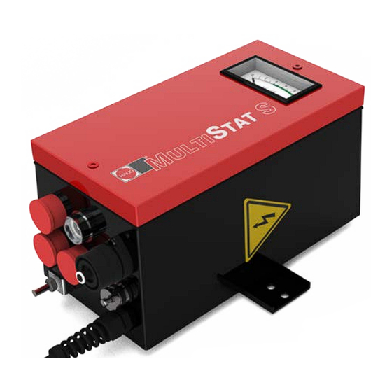
- Page 1 Operating instructions Discharging power pack Multistat S Ident number: 01.7870.000, 01.7870.050, 01.7871.000, 01.7871.050 Keep for future use! Static Line...
-
Page 3: Table Of Contents
Table of contents Operator instructions ..........4 Symbols used in operating instructions ......4 Symbols on the discharging power pack ......5 Safety ................6 Intended use ..............7 Product overview............8 Install ................9 Operate ..............14 Normal operation ............14 Normal operation and monitoring ........15 Troubleshooting ............ -
Page 4: Operator Instructions
Operator instructions 1 Operator instructions Before installation and commissioning read these operating instruction in full. Always observe the safety instructions. These operating instruction is a part of the product; make sure you retain them for later use or subsequent owners. The discharging power pack is maintenance free and operationally safe when used as intended. -
Page 5: Symbols On The Discharging Power Pack
Operator instructions Never dispose of with household garbage. Caution, danger spot warning! 1.2 Symbols on the discharging power pack WARNING! High voltage ATTENTION! Only plug in/unplug the ionizing unit at the HV terminal when the discharging power pack is switched off. -
Page 6: Safety
Safety 2 Safety Only the persons authorized by the operator may carry out tasks on the discharging power pack. The installer must be a trained and qualified electrician and read the operating instructions in full. The operator must read the operating instructions in full. When working on the discharging power pack, switch off the voltage supply and secure against inadvertent switching on. -
Page 7: Intended Use
In combination with an ionizing unit, electrostatic charges are neutralized in a production process. Always observe the installation and operating conditions indicated in these operating instructions. Warranty only covers products, accessories or spare parts of HAUG GmbH & Co. KG. -
Page 8: Product Overview
Product overview 3 Product overview A Fuse holder with fuse (Replacing fuse, refer page B Error indicator lamp (flashes yellow in the event of a defect) C Mains switch (lights up green when discharging power pack is switched on) D K1 signalling socket (monitoring) E K6 signalling socket (external reset) -
Page 9: Install
• Never install at a location subject to direct solar irradiation. 1. Check the model plate of the discharging power pack against the ordering data. In the event of damage to the discharging power pack, contact HAUG GmbH & Co. KG. 2. Before connecting, make sure that the correct supply voltage is available for the discharging power pack. - Page 10 Install 3. Place the discharging power pack at the desired location and attach with the enclosed retaining plate, if appropriate. • The operation of the discharging power pack is not affected by the position in which it is installed. • We recommend installing the discharging power pack with the HV terminals...
- Page 11 Install 6. Connect the discharging power pack to the supply voltage. Always connect the protective earth conductor (green-yellow) with a functioning protective earth of the mains. • Connecting the PE conductor via parts of a machine body is insufficient. • L = brown conductor •...
- Page 12 Install NOTE: Compliance with maximum connection length specifications is required. Use blind plugs to protect the unused HV connection points against environmental influences. Ensure that the blind plugs are clean, dry and free of grease. 8. If required, the signalling line K6 can be connected to the K6 signalling socket (E).
- Page 13 Install 9. If required, the signalling line K1 can be connected to the K1 signalling socket (D). • The K1 signalling socket can be used to monitor the correct function of the discharging power pack. • Relay contact rating: max. 24 V~ / 35 V=, max.
-
Page 14: Operate
Operate 5 Operate Preconditions: The discharging power pack and the ionizing unit are connected and installed as specified in the operator instructions. NOTE: After an error, the discharging power supply unit switches off the HV and the error lamp starts to flash with a delay of up to 20 seconds. This can be triggered by: •... -
Page 15: Normal Operation And Monitoring
Operate 5.2 Normal operation and monitoring To enable monitoring, connect the signalling line K1 (accessory) to the signalling socket K1 (D). NOTE: The relays of the K1 signal socket switch with a maximum delay of 20 seconds. 1. Switch on the discharging power pack using the mains switch (C). - Page 16 Operate Application examples (e.g. connection to PLC) Example 1: A Relay contact for mains failure B Relay contact for HV failure C1 Bridge 1 C2 Bridge 2 D Output E Input High-voltage Continuity (D and E) Normal operation Malfunction Example 2: A Relay contact for mains failure B Relay contact for HV failure...
-
Page 17: Troubleshooting
• Faults may only be eliminated by a trained and qualified electrician. NOTE: If the error cannot be removed in this way, return the discharging power pack and ionizing unit for checking to HAUG GmbH & Co. KG (the address is provided on the back of the envelope). Error Cause... -
Page 18: Replacing Fuse
Troubleshooting 6.1 Replacing fuse Damage to equipment! An incorrect fuse in the discharging power pack may cause a defect. This may result in a cable fire. • Only use fuses of the specified type. • Never use repaired fuses. • Never bridge the fuse. The unit type and the rated voltage are indicated on the nameplate. -
Page 19: Flow Chart
Troubleshooting 6.2 Flow chart The error indicator lamp flashes. Switch off discharging power pack and unplug ionizing units. Disconnect signalling line K1/K6 from the discharging power pack. Switch on the discharging power pack and wait 20 s. Flashes the error Discharging power indicator lamp? pack is faulty... -
Page 20: Accessories/Spare Parts
Accessories/spare parts 7 Accessories/spare parts Accessories and spare parts can be sourced from your authorized sales partner or directly from HAUG GmbH & Co. KG (the address is provided on the back of the envelope). Order Article Illustrations number Circular plug (K1) X –... - Page 21 Accessories/spare parts Order Article Illustrations number Control plug (K6) X – 7807 5 m shielded signalling line K6 with 06.8976.000 assembled plug 10 m shielded signalling line K6 with 06.8976.001 assembled plug 20 m shielded signalling line K6 with 06.8976.002 assembled plug Combicheck 12.7231.000...
-
Page 22: Technical Data
Technical data 8 Technical data 8.1 Key figures and specifications Reference temperature 23 °C HV connections High voltage ~ 6.7 ±1 kV Short circuit current approx. 5 mA Relay contact load K1 signal max. ~ 24 V/35 V=; max. 50 mA socket A pulse cannot be applied 8.2 Supply voltage... -
Page 23: Ambient Conditions
Technical data 8.3 Ambient conditions Never use in potentially explosive atmospheres. Use indoors only. Temperature: Rated range of use +5 to 45°C Limit range for storage and -15 to 60°C transport Relative humidity (RH): Rated range of use 20% to 65% RH Limit range for storage and 0 % to 85 % RH transport... -
Page 24: Connected Lengths
Technical data 8.4 Connected lengths Unit type Permissible Maximum Maximum connected ionizing bar ionizing bar length length Type A length Type B Discharging 18 m 18 m power pack Ionizing bar Type A EI RN, EI RNE, EI RA, EI RAE, EI RNOF, EI RAOF, EI HRN, EI HRA, EI HRE, EI HRAE, EI PS, EI PRX, EI PRV, EI SL, EIW Type B... -
Page 25: Housing
Technical data 8.5 Housing Protection type IP 54 Protection class Mains supply approx. 2,6 m fixed on unit Dimensions: Height 245 mm Width 130 mm Depth 130 mm Weight: 5 kg... -
Page 26: Taking Out Of Operation
Taking out of operation 9 Taking out of operation Electric shock hazard! The discharging power pack is operated electrically and generates a high electric voltage. Improper decommissioning may result in electric shock. • Decommissioning may only be carried out by a trained and qualified electrician. - Page 28 made by...
Need help?
Do you have a question about the Multistat S and is the answer not in the manual?
Questions and answers