
Related Manuals for Maxlogic ML-4218

Summary of Contents for Maxlogic ML-4218
- Page 1 COMMISSIONING, OPERATING AND MAINTENANCE MANUAL MODEL: MAXLOGIC SERIES SUB MODEL: CONVENTIONAL GAS ALARM PANEL, 8 ZONES, 16 RELAY OUTPUT...
-
Page 2: Table Of Contents
Panel Fuses Powering the Panel Panel Menu Technical Specifications Panel Models ANNEX ANNEX-A Panel Dimensions, Mounting Point, and Spare Parts ANNEX-B Connection Scheme ANNEX-C Panel’s front face Serigraphy ANNEX-D Scheme of Menu Functions KK-642.034 Rev.No:7 24.03.21 ML-4218 User Manual 2/17... -
Page 3: Introduction
1- INTRODUCTION Maxlogic ML-4218 is a 8 zone, 24V DC operating voltage conventional gas alarm panel. Gas alarm pane can work with carbon-mon- oxide, methane (natural gas), and LPG with 2 alarm stage gas detectors. Panel power supply unit has an automatic battery charger and charging control circuit. - Page 4 A complete system check must be carried out after commissioning. SIGNS USED ON THE DEVICE Sıgn Description Dangerous Voltage 230V AC Rated Voltage Protective Earth Attention! Static Safeguarded Work Area Two units 12V 7Ah battery required KK-642.034 Rev.No:7 24.03.21 ML-4218 User Manual 4/17...
-
Page 5: Mounting
4.3 Detection Period Inputs (Convansional Zone Lines) ML-4218 panels are produced with 8 zones. Each conventional zone input voltage is 24V DC. Gas detectors with volt-free change over contact and two alarm level; have been connected to conventional zone inputs. Detection zone inputs are non-locking. -
Page 6: Panel Outputs
KK-642.034 Rev.No:7 24.03.21 ML-4218 User Manual 6/17... -
Page 7: Control Buttons
W/Dog reset button This button is used to turn off “W/Dog Fault” LED (Annex-B Figure-12) LCD backliht Adjustment of the brightness of LCD screen can be done by the help of trimpot. (Annex-B Figure-14) KK-642.034 Rev.No:7 24.03.21 ML-4218 User Manual 7/17... -
Page 8: Panel Indicators
System locked at a cause of problems on processing the programs, then it is automatically reset and restarting. At this situation; “W/Dog Fault” LED indicators illuminates. “W/Dog Reset” button must be pushed to turn off this LED. (Annex-B Figure-11) Charge Fault It shows defection of the battery charge circuit. (Annex-B Figure-10) KK-642.034 Rev.No:7 24.03.21 ML-4218 User Manual 8/17... -
Page 9: Panel Fuses
3- Controlling the zones where alarm comes from. If the gas alarm is true; “Alarm Reset / Alarm” button must be pushed again to activate sounders and alarm relay, then evacuation process starts. KK-642.034 Rev.No:7 24.03.21 ML-4218 User Manual 9/17... -
Page 10: Panel Menu
“Zone enable” function. Then, “Feature On” feature changed to “Feature Off” by pushing “Right Arrow” and zone activated. At this time “Enable” and deactivated zones fault LED indicator turns off. KK-642.034 Rev.No:7 24.03.21 ML-4218 User Manual 10/17... - Page 11 After that, feature activated by pushing “Right arrow” button. “Feature on” message displayed on screen. Than from “Sounder delay” feature on 3rd access level (see section 10.2.1.) delay time must be determined. Finally, “Delay activated” feature on 2nd access level (see 10.1.1.) selected to “Feature on” condition. KK-642.034 Rev.No:7 24.03.21 ML-4218 User Manual 11/17...
- Page 12 Then same procedure repeating to deactivate the feature. “Feature on” message changed as “Feature off” message. 10.2.10 Activated / Disactivated RS-485 Outputs This feature is not active at this time. 10.2.11 Exit “Right arrow” button must be pushed to pass 3rd access level to 2nd access level. KK-642.034 Rev.No:7 24.03.21 ML-4218 User Manual 12/17...
-
Page 13: Technical Specifications
* Excluding batteries 1922 Mavili Elektronik Ticaret ve Sanayi A.Ş. Şerifali Mahallesi, Kutup Sokak No:27/1-2-4 Ümraniye TR-34775 İSTANBUL 1922-CPR-0774 EN 54-2, EN 54-4 ML-4218 Technical specifications: Please check KK-642.034 that is held by manufacturer. KK-642.034 Rev.No:7 24.03.21 ML-4218 User Manual 13/17... -
Page 14: Annex Annex-A Panel Dimensions, Mounting Point, And Spare Parts
KK-642.034 Rev.No:7 24.03.21 ML-4218 User Manual 14/17... -
Page 15: Annex-B Connection Scheme
KK-642.034 Rev.No:7 24.03.21 ML-4218 User Manual 15/17... -
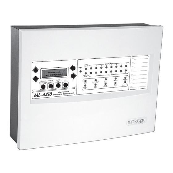
Page 16: Annex-C Panel's Front Face Serigraphy
KK-642.034 Rev.No:7 24.03.21 ML-4218 User Manual 16/17... -
Page 17: Annex-D Scheme Of Menu Functions
ANNEX-D Scheme of Menu Function KK-642.034 Rev.No:7 24.03.21 ML-4218 User Manual 17/17...
Need help?
Do you have a question about the ML-4218 and is the answer not in the manual?
Questions and answers