
Related Manuals for PicoQuant FluoTime 250

Summary of Contents for PicoQuant FluoTime 250
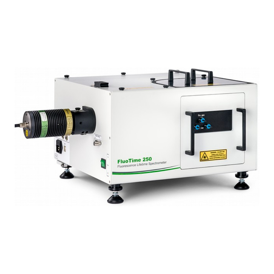
- Page 1 Setup Manual Automated, Compact, High Performance Fluorescence Lifetime Spectrometer Unpacking and setting up the hardware Setup Manual Document version 1.0.2...
-
Page 3: Table Of Contents
2.2. Before Unpacking..........................8 2.3. Opening of the wooden shipping crate..................... 9 Setting up the FluoTime 250........................10 3.1. Functional Grounding of the FluoTime 250 spectrometer..............10 3.2. Wiring of the FluoTime 250 spectrometer..................12 3.2.1. Power and laser trigger cables..................12 3.2.2. - Page 4 Remote Support Sessions Thank you very much for purchasing a FluoTime 250 lifetime spectrometer. We would like to offer you a spe - cial service: remote support. In order to arrange for a live remote session, please contact the PicoQuant Support Team at: https://support.picoquant.com...
-
Page 5: General Safety Information
/ damages resulting from operating the device outside of the normal usage defined in this manual. To unpack the crate in which the FluoTime 250 was shipped always use protec- tive gloves and strictly follow the instructions given in this manual. -
Page 6: Electrical Safety Instructions
WARNING! Visible and invisible laser radiation The FluoTime 250 can be used with laser diode heads that can emit visible, infrared, or UV light. Infrared or UV light is not visible to the eye! These diode lasers can emit laser light of up to class 3b / IIIb. Please refer to the labels affixed to the laser head for information on classification. -
Page 7: Laser Safety Labels
PicoQuant GmbH FluoTime 250 Setup Manual • The owner / operator is fully liable for all consequences resulting from the use of the laser for any purposes other than those listed in the operating manual. The laser may be operated only by persons who have been instructed in the use of this laser and the potential hazards of laser radiation. - Page 8 LDH laser heads. On the FluoTime 250 Several laser safety labels are affixed to the housing of the FluoTime 250, which are highlighted n red (Fig. 2. Fig. 2: Location of the laser safety labels on the FluoTime 250. The system is labeled in 4 positions and the signs indicate that access to a class 3B / IIIB laser beam when:...
-
Page 9: Remote Interlock Connector
PicoQuant does NOT endorse the use of non-approved third-party laser devices with the FluoTime 250 sys- tem. The end-user should not connect non-approved laser devices to or operate the FluoTime 250 with them. PicoQuant declines any responsibility and cannot be held liable for any direct or indirect damages to the users and/or instrumentation resulting from the use of non-approved third-party laser devices by the end- user. -
Page 10: Unpacking The Fluotime 250
FluoTime 250 Setup Manual 2. Unpacking the FluoTime 250 If you need to store the FluoTime 250 before installation, make sure that the closed crate is stored in a dry place (<70% rel. humidity) and at temperatures between +15° and +30 °C. -
Page 11: Opening Of The Wooden Shipping Crate
Remove all four side walls. • Carefully lift the different items out of the box. Since the FluoTime 250 itself is rather heavy (ca. 50 • kg), it needs be lifted out of the box by 2 people. Please check and observe local safety guide- lines regarding lifting heavy items. -
Page 12: Setting Up The Fluotime 250
IEC 60364-5-54: 2011 as well as the German standard DIN VDE 0100-540: 2012-06. Fig. 6: The grounding scheme for the FluoTime 250 connected to a PDL 820 and computer equipped with a TimeHarp 260 Pico TCSPC card. - Page 13 FluoTime 250 Setup Manual Fig. 7: The grounding scheme of the FluoTime 250 connected to a PDL 820, a PicoHarp 300 TCSPC unit and a computer. Fig. 8: Location of the grounding pins (indicated by red squares). Top left: on the FluoTime 250. Bottom left: on the back of the PDL 820 laser driver.
-
Page 14: Wiring Of The Fluotime 250 Spectrometer
FluoTime 250 Setup Manual 3.2. Wiring of the FluoTime 250 spectrometer The detailed cabling plan for your FluoTime 250 spectrometer can be found in the appendix of the user’s manual delivered with your system. All included cables are labeled on both ends. NOTICE The colors used in the depiction of cables in all wiring schemes are for illustrative purposes only. -
Page 15: Connecting The Detector
Fig. 11. Fig. 10: Wiring of the PMA detector with the FluoTime 250 terminal. Green: power cable, dark red: CAN cable, orange: shutter cable. Fig. 11: Wiring of the PMA Hybrid detector with the FluoTime 250 terminal. Green: power cable, dark red: CAN cable, orange: shutter cable. - Page 16 FluoTime 250 Setup Manual NIR-PMA detector If your FluoTime 250 system is equipped with an NIR-PMA detector, lock the Interlock connector at the Fluo- Time 250 terminal using the corresponding cable (see Fig. 12). Connect the Input connector of the NIR-PMA detector to the Output connector at the NIR-PMA controller (see Fig.
-
Page 17: Connecting The (Optional) Monochromator
If you purchased a FluoTime 250 equipped with the optional monochromator, please connect the power cable to the 24 VDC and Control connectors of the FluoTime 250 terminal panel to the Power and Signal connectors at the back of the monochromator (see Fig. 13). -
Page 18: Connecting The Detector Signal Cable To The Tcspc Unit
If your FluoTime 250 system is equipped with TimeHarp 260 Pico TCSPC card (which is already installed in the FluoTime 250 computer) and a PMA or PMA Hybrid detector, refer to the wiring scheme shown in Fig. 14. Please note that the signal input connector on the TimeHarp 260 Pico is marked as 1. - Page 19 Channel 1 input connector on the PicoHarp 300 (see Fig. 15). Fig. 15: Wiring scheme for the signal cable connecting the FluoTime 250 system to a PicoHarp 300 and a PMA (left) or PMA Hybrid (right) detector.
- Page 20 TimeHarp 260 PICO TCSPC card installed in the computer (Fig. 16). Please note that the signal input connector on the Time Harp 260 Pico is marked as 1. Fig. 16: Wiring scheme for the signal cable connecting the FluoTime 250 system with a TimeHarp 260 Pico TCSPC card and an NIR- PMA detector.
-
Page 21: Connecting The Trigger Cable
TimeHarp 260 PICO is labeled with an S, while the connector on the PicoHarp 300 is called “Channel 0”. Fig. 17: Wiring schema of the trigger cable for the FluoTime 250 system with the TimeHarp 260 PICO (left) and PicoHarp 300 (right) TCSPC electronics. -
Page 22: Setting Up The Tlc Sample Mounting Unit (Optional Component)
BATH100) to the water connections on the TLC50 sample mounting unit (see Fig. 19) by using the tubes delivered with your FluoTime 250. Attach one tube to the brass fitting on the top of the submersible pump and insert the other into the water tank (Fig. 19). Fill water into the water tank until the pump is covered. Plug the power cable of the submersible pump to the “Pump”... - Page 23 FluoTime 250 Setup Manual Fig. 19: Coupling of the coolant water tubes to the TLC50 sample mounting unit and Bath100. Top (from left to right): FluoTime 250 with sample mounting unit, bath controller unit and water tank with pump and tubing. Bottom left: connect tubing after removing the corresponding glands.
-
Page 24: Usb Connections
USB ports of the FluoTime 250 computer. Refer to Fig. 20 or Fig. 21, depending on your configuration. The PicoHarp 300 is ideally connected to a USB 3.0 port, while the FluoTime 250 and the PDL 820 laser driver should be connected to the ports on the additional USB-board that is already installed in the FluoTime 250 computer. -
Page 25: Attaching A Light Source
(Fig. 22). Fig. 22: a) laser input port of the FluoTime 250 (highlighted with a red box. b) label indicating the orientation of the laser heads polar- ization plane. c) laser head attached at the laser coupling port of the FluoTime 250. d) an LED head from the PLS Series connected to the FluoTime 250. -
Page 26: Inserting A Sample Mounting Unit
Fig. 24: Sliding a sample mounting unit into the FluoTime 250 Make sure that the sample chamber lid is closed (Fig. 25). Fig. 25: Sample chamber lid of the FluoTime 250 Your FluoTime 250 system is now ready for use and can be turned on (see next section). Page 24... -
Page 27: Starting The Fluotime 250
4. Starting the FluoTime 250 • Start by turning on all PicoQuant devices of the system such as the PicoHarp 300 TCSPC module (if present) and the laser driver. Refer to their dedicated manuals for further details. If present, turn on the temperature controller of the sample holder •... - Page 28 Finally select the desired measurement conditions and start the measurement. For using the Easy- • Tau2 software and performing measurements with the FluoTime 250, please consult the video and written tutorials stored on the delivered FluoTime 250 computer. The EasyTau2 software has an extensive online help function that can be opened by pressing the F1 key.
-
Page 29: Performance Check
Check the FluoTime 250 configuration ◦ Switch on the laser driver, PicoHarp 300 (if available), and the FluoTime 250 spectrometer Turn on the PC and start EasyTau2 software. Refer to section 4 Starting the FluoTime 250. ◦ Select Customized Measurement mode ◦... -
Page 30: Measure An Instrument Response Function (Irf) Of A Connected Laser
PicoQuant GmbH FluoTime 250 Setup Manual 5.2. Measure an instrument response function (IRF) of a connected laser Couple the corresponding laser head to the laser driver and FluoTime 250 spectrometer. ◦ Switch the laser driver, FluoTime 250 and computer on ◦... - Page 31 PicoQuant GmbH FluoTime 250 Setup Manual Fig. 31: Time-resolved measurement mode. Press “Optimize for IRF” button ( , Fig. 31). The following window will appear (Fig. 32): ◦ Fig. 32: Optimize for IRF window. ◦ Tick “Excitation Attenuator” and “Detection Attenuator” check boxes Press “Start Optimization”...
- Page 32 PicoQuant GmbH FluoTime 250 Setup Manual Press “Start” button and collect IRF signal (Fig. 34). ◦ Fig. 34: Start measuring the IRF. When the measurement has finished, press the “Save” button (Fig. 35). The data will be saved in ◦...
- Page 33 PicoQuant GmbH FluoTime 250 Setup Manual Plot the IRF by clicking on the corresponding “Plot data” button in the toolbar menu of the Easy- ◦ Tau2 software. A window as shown below will appear (Fig. 36): Fig. 36: Plotting of the measured IRF and calculation of the FWHM of the IRF.
-
Page 34: Fluorescence Decay Measurement Of The Reference Polymer Block (If The Reference Polymer Block Was Ordered)
Appendix. Moreover, a measurement script is included on the USB thumb drive delivered with the FluoTime 250 in the “Scripts” folder under the name: Ref_x_LDH-x-x-xxx_Filter-x (where Ref_x is the name of the reference fluorescence poly- mer block, LDH-x-x-xxx is the laser head used for the measurement, Filter-x is the long-pass emis - sion filter used). - Page 35 PicoQuant GmbH FluoTime 250 Setup Manual Press “Open Script...” button and open the corresponding script-file from the USB thumb drive ◦ (Fig. 38). ◦ Press “Run Script” button to execute the script. After finishing the measurement, perform an analysis of the measured decay (refer to the tutorial ◦...
-
Page 36: Turning Off The Fluotime 250
Shut down the EasyTau2 software in order to avoid data loss. • Switch the laser driver into its stand-by mode before turning it completely off. • Turn off the FluoTime 250 via the main switch (Fig. Fehler: Verweis nicht gefunden). • Fig. 39: Turning the FluoTime250 off. NOTICE... -
Page 37: Support
PicoQuant GmbH FluoTime 250 Setup Manual 7. Support 7.1. Returning Products for Repair Should you encounter serious problems that require sending the device in for inspection / repair, please con- tact us first at: https://support.picoquant.com support@picoquant.com and request an RMA number before shipping the device. -
Page 38: Legal Terms
FluoTime 250 Setup Manual 8. Legal Terms 8.1. Copyright Copyright of this manual and on-line documentation belongs to PicoQuant GmbH. No parts of it may be reproduced, translated, or transferred to third parties without written permission of PicoQuant 8.2. Trademarks Other products and corporate names appearing in this manual may or may not be registered trademarks or subject to copyrights of their respective owners. - Page 39 PicoQuant GmbH FluoTime 250 Setup Manual All information given here is reliable to our best knowledge. However, no responsibility is assumed for possible inaccuracies or omissions. Specifications and external appearances are subject to change without notice. PicoQuant GmbH P +49-(0)30-1208820-0...
Need help?
Do you have a question about the FluoTime 250 and is the answer not in the manual?
Questions and answers