
Related Manuals for Sinosun 1710 Series

Summary of Contents for Sinosun 1710 Series
- Page 1 1710/2710/4710/971 0 Series 1710IP/2710IP/4710IP/971 0IP Series 150/230/400/900MHz Bands Data Transceivers 05-3305A01, Rev. E September 2023...
- Page 2 QUICK START GUIDE Below are the basic steps for installing the transceiver. See “INSTALLATION” on Page 5 of this guide for detailed instructions. Install and connect the antenna system to the radio • Use good quality, low loss coaxial cable. Keep the feedline as short as possible. •...
-
Page 3: Table Of Contents
TABLE OF CONTENTS 1.0 GENERAL ................... 1 1.1 Introduction ..................1 1.2 Applications ..................2 Point-to-Multipoint, Multiple Address Systems (MAS) ...... 2 Point-to-Point System ............... 3 Continuously-Keyed versus Switched-Carrier Operation....3 Single-Frequency (Simplex) Operation..........4 1.3 Model Number Codes ..............4 1.4 Contents of Standard Shipping Packages ........ - Page 4 DEVICE [DCE, CTS KEY]............... 25 DKEY ....................26 DIN [ON/OFF] ................. 26 DLINK [ON/OFF/xxxx]..............26 DTYPE [NODE/ROOT] ..............26 DUMP ..................... 26 EMP [ON/OFF]................26 HREV ....................27 INIT ....................27 INIT [x710] ..................27 INIT [x720] ..................27 KEY....................28 MODEL ................... 28 MODEM [xxxx, NONE]..............
- Page 5 ISO 9001 Registration WDS adheres to this internatio nally accepted quality system standard. Quality Policy Statement We, the employees of sinosun, LLC , are committed to achieving total customer satisfaction in everything we do. Total Customer Satisfaction in: • Conception, design, manufacture and marketing of our products.
- Page 6 Antenna Installation Warning 1. All antenna installation and servicing is to be performed by qualified technical personnel only. When servicing the antenna, or working at distances closer than those listed below, ensure the transmitter has been disabled. Output is measured at the antenna terminal of the transmitter. The antenna(s) used for this transmitter must be fixed-mounted on outdoor permanent structures to provide the minimum separation distances described in this filing for satisfying RF exposure...
- Page 7 unauthorized modification or changes to this device without the express approval of Wireless Data Systems may void the user’s authority to operate this device. Furthermore, this device is intended to be used only when installed in accordance with the instructions outlined in this manual.
- Page 8 Distress Beacon Warning In the U.S.A., the 406 to 406.1 MHz band is reserved for use by distress beacons. Since the radio described in this manual is capable of transmit- ting in this band, take precautions to prevent the radio from transmitting between 406 to 406.1 MHz in U.S.
-
Page 9: General
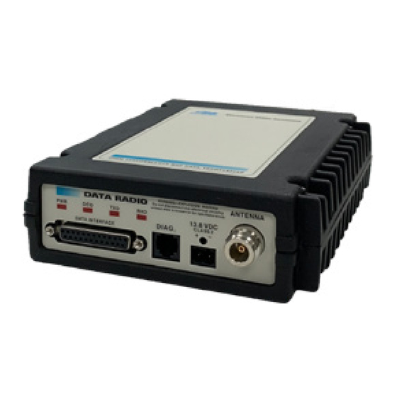
1.0 GENERAL 1.1 Introduction This guide presents installation and operating instructions for the 1710A/2710A/4710A/9710A and 1710C/2710C/4710C/9710C Series (150/230/350/400/900 MHz) digital radio transceivers. These transceivers (Figure 1) are data telemetry radios designed to operate in a point-to-multipoint environment, such as electric utility Supervisory Control and Data Acquisition (SCADA) and distribution automation, gas field automation, water and wastewater SCADA, and online transaction processing applications. -
Page 10: Applications
NOTE: Some features are not available on all radios, based on the options purchased and the applicable regulatory constraints for the region in which the radio operates. 1.2 Applications Point-to-Multipoint, Multiple Address Systems (MAS) This is the most common application of the transceiver. It consists of a central master station and several associated remote units as shown in Figure 2. -
Page 11: Point-To-Point System
Point-to-Point System Where permitted, the transceiver can also be used in a point-to-point system. A point-to-point system consists of two radios, one serving as a master and the other as a remote (Figure 3). This system provides a sim- plex or half-duplex communication link for the transfer of data between two locations. -
Page 12: Single-Frequency (Simplex) Operation
Single-Frequency (Simplex) Operation Single-frequency operation (also known as simplex) is a special case of switched-carrier operation. Single frequency operation is automatically selected whenever the transmit and receive frequencies are set to the same value. Simplex mode results in slower polling because the TX syn- thesizer must move off the RX channel to receive, and back to transmit. -
Page 13: Accessories
1.5 Accessories The transceiver can be used with one or more of the accessories listed in Table 3. Contact us for ordering information. Table 3. Optional Accessories for 1710/2710/4710/9710 Transceivers Accessory Description Power Supply Kit Provides nominal 13.8 Vdc from a 01-3682A01 120 Vac power source. -
Page 14: Installation Steps
Invisible place holder REMOTE TERMINAL UNIT ANTENNA SYSTEM RADIO TRANSCEIVER 13.8 VDC POWER CABLE LOW-LOSS FEEDLINE 13.8 VDC 2.5 A (MINIMUM) POWER SUPPLY Figure 4. Typical Remote Station Arrangement 2.1 Installation Steps Below are the basic steps for installing the transceiver. In most cases, these steps alone are sufficient to complete the installation. -
Page 15: Transceiver Mounting
4. Measure and install the primary power for the radio. The red wire on the provided power cable is the positive lead; the black is negative. o transceivers in nega- Only use the 1710/ 2 710/4710/9710radi CAUTION tive-ground systems. POSSIBLE Connection to a positive-ground system or an accidental reversal EQUIPMENT of the power leads can damage the transceiver. - Page 16 Invisible place holder 8.5 in. 216 mm 6.63 in. 168 mm ALTERNATE POSITION 5.625 in. 143 mm Figure 5. Transceiver Mounting Dimensions Using screws longer than 1/4 inch (6 mm) to attach the brackets CAUTION to the radio might damage the internal PC board. Use only the POSSIBLE supplied screws.
-
Page 17: Antennas And Feedlines
2.3 Antennas and Feedlines Antennas The transceiver can be used with a number of antenna styles. The exact style depends on the physical size and layout of the radio system. A directional Yagi (Figure 6) or corner reflector antenna is generally rec- ommended at remote sites to minimize interference to and from other users. -
Page 18: Power Connection
Table 5. Length vs. Loss in Coaxial Cables at 960 MHz 10 Feet 50 Feet 100 Feet 500 Feet (3.05 Meters) (15.24 Meters) (30.48 Meters) (152.4 Me- Cable Type ters) RG-8A/U 0.85 dB 4.27 dB 8.54 dB 42.70 dB 1/2 inch HELIAX 0.23 dB 1.15 dB 2.29 dB... -
Page 19: Data Interface Connections
2.6 Data Interface Connections DATA INTERFACE Connect the transceiver’s connector to an external DTE data terminal that supports the EIA-232 (formally RS-232) format. The transceiver supports autobaud asynchronous data rates of up to DATA INTERFACE 19200 bps. The data rate at the connector might differ from the data rate used over the air. -
Page 20: Using The Radio's Sleep Mode
Table 6. DATA INTERFACE Connector Pinouts (Continued) Input/ Number Output Pin Description Do not connect—Reserved for future use. PTT—Push-to-Talk. This line is used to key the radio with an active-high signal of +5 Vdc. User-Programmable Output 2—EIA-232-compatible output controllable though GE MDS’ InSite NMS program. See “User-Programmable Interface Output Functions”... -
Page 21: System Example
Enable Sleep Mode through RTU control by asserting a ground on Pin DATA INTERFACE 12 of the radio's connector. When Pin 12 is opened, the radio will be ready to receive data after a delay period that varies MODEM NONE with modem type. -
Page 22: Led Indicators
If all parameters are correctly set, start radio operation by following these steps: 1. Apply DC power to the transceiver. 2. Observe the LED status panel for the proper indications (Table 3. If not done earlier, refine the antenna heading of the station to maxi- mize the received signal strength (RSSI) from the master station. -
Page 23: Transceiver Programming
Invisible place holder SIGNAL LEVEL (dBm) Figure 8. RSSI vs. Vdc (Typical) 4.0 TRANSCEIVER PROGRAMMING DIAG To program and read the transceiver, use the radio’s RJ-11 (Diagnostics) connector with a personal computer through a diagnostic cable . Table 9 ) and detailed descriptions This section c ontains a reference chart ( for each user command. -
Page 24: Pc Connection And Startup
4.2 PC Connection and Startup A、Follow the steps below to prepare the radio for PC programming. a.install " SCADA(X710) Radio Configuration Software " Invisible place holder b.operation software. 1.double click the icon 05-3305A01, Rev. E... - Page 25 2.click on the opening screen 3.select " Commport " read the radio parameters 4. radio parameters 5. select " Radio " program the radio parameters 05-3305A01, Rev. E...
- Page 26 B、Win7 Win10 operating system selection, folder the following icons, follow the prompts to install the software C、Through the serial assistant SSCOMV 5.13.1, enter the X710 radio to change the transmission and reception frequency, data format and other parameters 1. Connect the diagnostic cable of X710 radio, open the SSCOM V5.13.1 Serial port assistant software, set the data format "1200 8N1", and open the serial port.
-
Page 27: Keyboard Commands
4.3 Keyboard Commands Table 9 on Page 19 is a reference chart of software commands for the transceiver. Programmable information is shown in brackets [ ] fol- Section 4.4, Detailed Command lowing the command name. See Descriptions (Page 21) for detailed command descriptions. Entering Commands To enter a command, type the command, and then press the key. - Page 28 Table 9. Command Summary Command name Function ALARM Read current operating condition of radio. Details Page 21 AMASK [0000 0000–FFFF Set or display hex code identifying which events FFFF] Details Page 21 trigger an alarm. ASENSE [HI/LO] Set or display the state of the alarm output signal Details Page 23 to ACTIVE HI or ACTIVE LO.
-
Page 29: Detailed Command Descriptions
Table 9. Command Summary (Continued) Command name Function RSSI Display the Received Signal Strength Indication. Details Page 29 RTU [ON/OFF/0-80] Re-enables or disables the radio’s internal RTU Details Page 29 simulator and sets the RTU address. RX [xxx.xxxx] Set or display receiver frequency. Details Page RXLEVEL [–20 to +6] Set or display the receive audio input level. -
Page 30: Alarm
Alarm Mask ALARM The ALARM command displays a summary of the radio’s current oper-ating condition. An eight-digit hexadecimal code is presented that can be decoded as described in “Major Alarms vs. Minor Alarms” on Page 33. AMASK [0000 0000–FFFF FFFF] The AMASK command displays or sets a mask indicating which events cause the alarm output signal to be active. -
Page 31: Asense [Hi/Lo]
Table 10. Alarm Event Codes and Hex/Binary Values Alarm Code Event Number Text Message 32-bit Binary Equivalent (hex) Data framing error 0000 2000 0000 0000 0000 0000 0010 0000 0000 0000 Reserved Configuration error 0000 0800 0000 0000 0000 0000 0000 1000 0000 0000 Running on battery 0000 0400 0000 0000 0000 0000 0000 0100 0000 0000... -
Page 32: Baud [Xxxxx Abc]
BAUD [xxxxx abc] Data Interface Port This command sets (or displays) the communication attributes for the Baud Rate DATA INTERFACE DIAG port. It has no effect on the RJ-11 port. xxxxx The first parameter ( ) is baud rate. Baud rate is specified in bits-per-second (bps) and must be set to one of the following speeds: 1200, 2400, 4800, 9600, or 19200. -
Page 33: Ckey [On-Off]
ON–OFF Key TX command enables or disables the continuously-keyed func- Continuously tion of the radio. When is set to , the radio is continuously keyed and the Timeout Timer is disabled. CTS 0–255 (clear-to-send) command selects or displays the timer value Clear-to-Send Time associated with the CTS line response. -
Page 34: Dkey
DKEY Unkey Transmitter This command deactivates the transmitter after it has been keyed with command. DIN [ON/OFF] DIN ON When is selected, the “not” PTT line (Pin 16 on the DB-25 con- Digital Input nector) is re-defined as a digital input for network-wide diagnostics. See “User-Programmable Interface Output Functions”... -
Page 35: Hrev
HREV Hardware Revision This command displays the transceiver’s hardware revision level. If nothing is displayed, the hardware revision level was not programmed by the factory. INIT INIT command is used to re-initialize the radio’s operating parame- Initialize EEPROM Defaults ters to the factory defaults. This is helpful when trying to resolve con- figuration problems that might have resulted from the entry of one or more improper command settings. -
Page 36: Key
DKEY TX Key This command activates the transmitter. See also the command. MODEL This command displays the radio’s model number code. Model Number Code MODEM [xxxx, NONE] This command selects the radio’s modem characteristics. For digital Analog/Digital Modem Selection 9600 19200 operation, enter (WDS x710A) or... -
Page 37: Rssi
Use this command to display or program the desired RF forward output power setting of the radio. The command parameter is specified in dBm and can range from 20 to 37. The default setting is 37 dBm (5 W). SHOW To read the actual (measured) power output of the radio, use the command. -
Page 38: Rxlevel [-20 To +6]
RXLEVEL [–20 to +6] RXLEVEL command RX Audio Output selects or displays the receive output level Level DATA INTERFACE present on Pin 11 of the ’s DB-25 connector. Use this MODEM NONE function in mode with analog audio. RXTOT [NONE, 1-1440] RXTOT Loss of RX Data command selects or displays the receive time-out timer value... -
Page 39: Srev
DIAG Using the SNR command causes the port to enter an update mode, and the SNR is updated and redisplayed every 2 sec. The SNR continu- ENTER ously updates until you press the key. SREV Software/Firmware This command displays the software revision level of the transceiver Revision Level firmware. -
Page 40: Txlevel [-20 To +6, Auto]
TXLEVEL [–20 to +6, AUTO] TXLEVEL command TX Audio Input Level selects or displays the transmit audio input level DATA INTERFACE expected on Pin 9 of the ’s DB-25 connector from an DATA INTERFACE external modem present on Pin 11 of the ’s DB-25 MODEM NONE connector. -
Page 41: Event Codes
5.2 Event Codes When an alarm condition exists, the transceiver creates a code that can DIAG be read on an HHT connected to the port. These codes can help resolve many system difficulties. Refer to Table 11 (Page 34) for a def- inition of the event codes. -
Page 42: Event Code Definitions
Event Code Definitions Table 11 contains a listing of all event codes reported by the transceiver. Table 11. Event Codes Event Event Code Class Description Major Improper software detected for this radio model. Major The model number of the transceiver is unprogrammed. Major One or both of the internal programmable synthesizer loops is reporting an out-of-lock condition. -
Page 43: Technical Reference
6.0 TECHNICAL REFERENCE 6.1 1710A/C, 2710A/C, 4710A/C, 9710A/C Transceiver Specifications GENERAL Frequency Range*: 1710A/C 2710A/C 4710A/C 9710A/C 130-174MHz 220-240MHz 330–512MHz 800–960 MHz * with one or more sub-bands as permitted by regulatory agencies: 1710: 130-150MHz,150-174MHz 4710: 330-350MHz,350-370MHz,370-400MHz,400-430MHz, 430-450MHz,450-480MHz,480-512MHz 9710: 800-860MHz,860-900MHz,900-960MHz Frequency Stability ±1.0 ppm RECEIVER... -
Page 44: Helical Filter Adjustment
FCC Identifiers: E5MDS9710N (928–960 MHz) E5MDS9710N-1 (806–940 MHz E5MDS4710 (403–512 MHz) DATA CHARACTERISTICS Connector: DB-25 Female Data Interface Rates: 110 bps to 38.4 kbps1200, 2400, 4800, 9600, 19200, 38400 bps—asynchronous Data Latency: 10 ms maximum, including RTS/CTS delay Byte Length: 10 or 11 bits PRIMARY POWER Voltage... -
Page 45: Performing Network-Wide Remote Diagnostics
4. Measure the radio’s RSSI using one of the following methods: •With an HHT or PC (see Section 4.0, TRANSCEIVER PROGRAM- MING Page 15). •With MDS Radio Confi guration Software (see Section 6.5, Upgrading the Radio’s Software Page 40). DATA INTERFACE •... - Page 46 Invisible place holder DTYPE NODE DTYPE NODE DTYPE NODE TO DATA PORT DIAGNOSTICS PORT DTYPE ROOT MASTER STATION ROOT DIAGNOSTICS DATA (TO InSite) PAYLOAD DATA (TO SCADA APPLICATION) HOST COMPUTER Figure 13. Network-Wide Remote Diagnostics Setup If a PC is connected to any radio in the network, you can perform intru- sive polling (polling that briefly interrupts payload data transmission).
-
Page 47: User-Programmable Interface Output Functions
DLINK ON DLINK [baud rate] 4. Use the commands to configure the diagnostic link protocol on the RJ-11 port of each node radio. 5. Connect same-site radios using a null-modem cable at the radios’ diagnostic ports. 6.Connect a PC with InSite software installed to the root DIAG radio, or to one of the nodes, at the radio’s port (this PC can... -
Page 48: Upgrading The Radio's Software
Invisible place holder Green Indicates current output state at associated radio transceiver is “high”. Click to set output to “low”. Figure 15. MDS InSite Radio Device User I/O Settings (Bottom Left-hand Corner of Network Wide Radio Configuration Screen) These output-only pins are designed for low switching rates and do not pass high-speed data, nor are they suitable for latency-sensitive remote controls. -
Page 49: External Orderwire Module
Software upgrades are distributed as ASCII files with an “.S28” exten- sion. These files use the Motorola S-record format. When the download is activated, the radio’s LED flashes rapidly to confirm that a download is in process. The download takes approximately 2 min. NOTE: If a download fails, the radio is left unprogrammed and inop- erative. -
Page 50: Operation
12-1307A01 without PTT; 12-1307A01 with PTT) can be purchased from us. Handsets must have carbon microphone elements installed. Dynamic microphones do not work with the module. Handsets with a push-to-talk (PTT) button are supported and recommended, as background noise can activate the VOX circuit and interrupt the payload data. -
Page 51: Dbm-Watts-Volts Conversion Chart
6.7 dBm-Watts-Volts Conversion Chart Table 13 is provided as a convenience for determining the equivalent wattage or voltage of an RF power expressed in dBm. Table 13. dBm-Watts-Volts Conversion—for 50 Ohm Systems dBm V dBm V dBm mV dBm µV 100.0 200W .225 1.0mW... -
Page 52: Wdsx710 Ip Series Instructions For Use
7.0WDSx710 IP Series Instructions for Use WDSx710IP series adds the function of Ethernet interface data transmission and reception, and the function is implemented as follow 7.1 Data transmission radio based on adding serial port gateway No need for other more operations, only need the terminal equipment to connect to the Ethernet port to carry out network port transparent transmission, the recommended number of bits transmitted per unit time in this mode ≤... - Page 53 In this scenario: The user's serial device connects to the serial port of the serial device server. The PC or device on the network side works in UDP mode. The serial device server works in UDP mode and completes the mutual forwarding of data between the two.
- Page 54 ④Enter the IP address of the serial device server in the browser, enter the user name and password to log in, and the initial user name and password are admin. ⑤Configure parameters, enter the web interface, click Serial Port Configuration, and configure relevant parameters according to the actual situation.
- Page 55 If you send a UDP packet from computer A to computer B through the SSCOM serial port & network debugging tool: First, enter 192.168.16.253 (configurable) through the browser to enter the serial device server management page of the two X710 IP stations connected to computer A and computer B respectively Enter the IP address and port consistent with the above figure in the lower left corner of SSCOM Serial Port &...
- Page 56 Computer A (IP: 192.168.16.5) After successful setup, use the same steps to set Computer B (IP: 192.168.16.5), After the settings are completed, UDP data can be sent and received in both directions, and the connectivity of the link can be successfully verified. 05-3305A01, Rev.
- Page 57 The radio must be properly packed for return to the factory. The original shipping container and packaging materials should be used whenever possible. All factory returns should be addressed to: Shenzhen Sinosun Technology Co., Inc. Customer Service Department 3A17,South Plaza Cangsong Building, Tairan Industry & Trade Zone...
- Page 58 Digital Signal Processing—See DSP. 44 Feedlines 9 Display Filter, helical, adjustment 36 alarm status (STAT command) 31 Frame, defined 45 alarm triggers (AMASK command) 21 Frequency all programmed settings (DUMP command) 26 adjusting helical filter when changed 36 baud rate and encoding (BAUD command) 24 setting.
- Page 59 Interface Output Functions 39 Orderwire Module 41 Intrusive diagnostics (defined) 45 Output, 9.9 Vdc regulated, pinout (Pin 19) 12 OWM command 28 OWN command 28 Owner’s message, set/display. See OWM command KEY command 28 Owner’s name, set/display. See OWN command Keyboard Commands Command Summary 19 Entering Commands 17...
- Page 60 unsquelched signal (Pin 10) 11 receiver 36 Redundant operation, defined 46 receiver system 35 Remote transceiver 35–36 Station, defined 46 transmitter 35 Station, illustrated 6 transmitter system 35 Resetting SREV command 31 Standing Wave Ratio—See SWR. 46 Hand-Held Terminal (HHT) (SHIFT,CTRL,SPACE keys) 16 STAT command 31 transceiver (INIT command) 27...
- Page 61 Shenzhen Sinosun Technology Co., Ltd. 3A17,South Plaza Cangsong Building, Tairan Industry & Trade Z one , Futian District, Shenzhen,Guangdong, China Phone: (86 )755-83849 417 F ax:(86 )755-83849 434 www.sinsosun.cn W eb: E-Mail: sales2@ sinosun.cn...
Need help?
Do you have a question about the 1710 Series and is the answer not in the manual?
Questions and answers