
Related Manuals for Hema HM-DVR22

Summary of Contents for Hema HM-DVR22
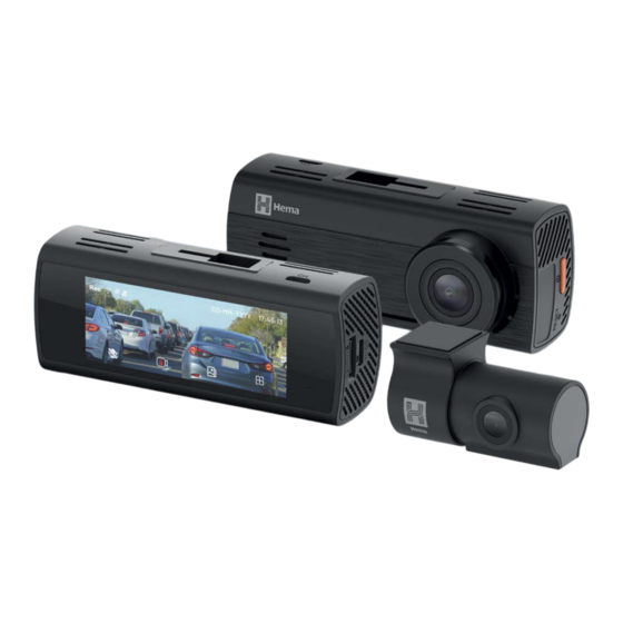
- Page 1 HM-DVR22 Dual Channel Dash Camera with 3.2" IPS Screen User Manual hema.com.au | hema.co.nz...
-
Page 3: Table Of Contents
7.0 BEFORE INSTALLING YOUR DASH CAMERA ........... 8 7.1 Inserting The Micro SD Card ������������������������������������������������������������������������������8 7.2 Fitting The 3M Mount To The Dash Camera ��������������������������������������������������8 8.0 INSTALLATION INSTRUCTIONS ................9 8.1 HM-DVR22 Installation ���������������������������������������������������������������������������������������9 8.2 Rear Camera Installation ���������������������������������������������������������������������������������� 10 9.0 THE 3-WIRE SMART HARDWIRE KIT ..............11 10.0 PRODUCT INFORMATION ..................12 11.0 FEATURES ...........................12 11.1 Hardwire Package Contents ����������������������������������������������������������������������������... - Page 4 15.1 Auto Power On/Off ������������������������������������������������������������������������������������������� 32 15.2 Formatting The Inserted Micro SD Card ������������������������������������������������������� 32 15.3 Setting The Date And Time ������������������������������������������������������������������������������ 33 15.4 Screen Menu ������������������������������������������������������������������������������������������������������� 34 15.5 Event Video Recording ������������������������������������������������������������������������������������ 35 15.6 Play Back Or Delete Recorded Files �������������������������������������������������������������� 36 15.7 Settings Menu ����������������������������������������������������������������������������������������������������� 37 15.7.1 V ideo Settings ����������������������������������������������������������������������������������������� 38 15.7.2 S ystem Settings �������������������������������������������������������������������������������������� 40 16.0 DOWNLOADING AND INSTALLING THE HEMA DVR APP ......42...
- Page 5 17.0 HEMA DVR APP OPERATION ................. 44 17.1 App Video Playback ������������������������������������������������������������������������������������������� 44 17.2 Downloading Videos From The App �������������������������������������������������������������� 45 17.3 Sharing Videos On Social Media ��������������������������������������������������������������������� 45 17.4 HM-DVR22 App Settings Cont' ���������������������������������������������������������������������� 46 18.0 WARRANTY TERMS AND CONDITIONS ............47 18.1 Indemnity ������������������������������������������������������������������������������������������������������������� 47 18.2 Warranty And Warranty Disclaimer ��������������������������������������������������������������� 48 18.3 Limitations of Liability ��������������������������������������������������������������������������������������� 49...
-
Page 6: Caution
CAUTION • Please ensure you are using your Dash Camera within your countries’ road laws. Please make sure you are familiar with your local road legislation before use. • The time and date needs to be set before you start recording. • The notifications provided by this Dash Camera are to be used as a guide only. Please drive according to the actual conditions on the road. • The system is for non-commercial use only, and within the limits permitted by the relevant laws. • Avoid using the Dash Camera in the vicinity of any devices that emit radio interference (eg. microwave ovens). PLEASE NOTE: It is normal for the Dash Camera to get warm during use. BATTERY WARNING • Always power the Dash Camera using the provided charger or hardwire kit. • Never dismantle the Dash Camera. • Do not dispose of the Dash Camera in fire. • Dispose the Dash Camera in accordance with local regulations. -
Page 7: Notes On Micro Sd Card
NOTE: Formatting the Micro SD card will delete all information on the inserted Micro SD Card and prepare the card for use with the Dash Camera. FORMATTING THE INSERTED MICRO SD CARD Please download the Hema DVR App and connect your Dash Camera with the downloaded app by following the steps as mentioned on "15.2 Formatting The Inserted Micro SD Card" on page 32. NOTES ON INSTALLATION 1. For best results, we recommend that the Dash Camera is installed near the rear view mirror, or at the top centre of the windscreen. -
Page 8: Introduction
INTRODUCTION Thank you for purchasing a Hema Dash Camera. We have designed this product for a better driving experience with enhanced safety features. Our products, like most after-market safety enhanced devices, are designed to assist and aid the driver, not to replace the manual function of the person operating the vehicle. Please read through these instructions before attempting to install this product. For the latest manual and product updates, please visit our website at www.hema.com.au or www.hema.co.nz PACKAGE CONTENTS HM-DVR22 1080P Internal Rear 6m Rear Camera Electrostatic Dash Cam Camera Cable Film x2 12V/24V 3M Adhesive User Spare 3M Adaptor Sticker Manual Adhesive x1... -
Page 9: Product Overview
PRODUCT OVERVIEW FRONT CAMERA (FIG. 1) 1. Function Keys 2. Microphone 3. Display Screen 4. 3M Mount Slot 5. Heat Dissipation Vents 6. Micro SD Card Slot 7. Mini USB Connector (for power) 8. Power Button 9. Reset Button 10. Speaker Vent 11. Camera Lens 12. Indicator LED (turns green when recording) 13. Micro USB Connector (Connect to Rear Camera) FIG. 1 REAR CAMERA (FIG. 2) 1. -
Page 10: Before Installing Your Dash Camera
BEFORE INSTALLING YOUR DASH CAMERA INSERTING THE MICRO SD CARD Please insert the memory card into the Micro SD Card slot with the chip contact surface facing up. Insert it until your hear a click sound. FITTING THE 3M MOUNT TO THE DASH CAMERA Insert the 3M bracket into the mounting hole, and slide to your left. -
Page 11: Installation Instructions
INSTALLATION INSTRUCTIONS HM-DVR22 INSTALLATION 1. OPTIONAL: The electrostatic film helps for easy removal of the Dash Camera from the windscreen and is included in package contents. Select the electrostatic film from the box and install it on the front windshield in the recommended position as shown. Please wipe the glass before installation and push out any air bubbles between the static film and the glass before installation. 2. Remove the protective film from the HM-DVR22 mounting bracket and position the Dash Camera in the middle of the electrostatic film. Press down the base of the bracket by hand for 30 seconds to ensure that the adhesive is attached to the electrostatic film, and adjust the camera until its lens is capturing the entire road. 3. Run the Dash Camera charging cable along the top of the front windscreen through the A-pillar and around and under glove box to the car's 12V/24V adaptor port. Connect the 12V/24V adaptor to the car power. -
Page 12: Rear Camera Installation
REAR CAMERA INSTALLATION 1. Install the electrostatic film on the rear windscreen in one of the recommended positions as shown in the diagram. Please wipe and clean the windscreen before installation and push out any air bubbles between the electrostatic film and the glass. 2. Remove the protective film from the rear camera bracket and select either the top or bottom of the rear windscreen to position the rear camera. 3. Press down the base of the bracket by hand for about 30 seconds to ensure that the adhesive sticker is properly attached to the electrostatic film. 4. Connect the rear camera to the HM-DVR22 using the supplied rear camera cable. Run the cabling either through the roof lining or under the carpet. 5. Adjust the angle of the rear camera accordingly to ensure that you have a good rear view from your vehicle. -
Page 13: The 3-Wire Smart Hardwire Kit
THE 3-WIRE SMART HARDWIRE KIT IMPORTANT: Refer to your vehicle owner’s manual to determine: • Location of the fuse box • How to access the fuse box • The type of fuse tap required It is highly recommended that you thoroughly read the installation instructions in this user manual. If you are not comfortable with the process, please seek further assistance from an authorised technician. -
Page 14: Product Information
If there are any issues with your dashcam, please refer them to your dasham manufacturer. 10.0 PRODUCT INFORMATION Get continuous power for your dashcam. The 3-Wire Smart Hardwire Kit connects to your vehicle battery through your vehicle’s fuse box and provides continuous power to your dashcam even when the engine is turned off. It includes several fuse tap options that suit most vehicles and your dashcam connects to the hardwire kit via the Mini USB connector. For the latest manual and product updates, please visit hema.com.au or hema.co.nz. 11.0 FEATURES • Suitable for use in cars and trucks with with a 12V or 24V battery. • Provides continuous power to your dashcam even when your vehicle is turned off. • Battery Drain Protection safeguards your dashcam from draining your vehicle’s battery. Your battery will stop providing power to your dashcam if your battery level gets too low. -
Page 15: Hardwire Package Contents
11.1 HARDWIRE PACKAGE CONTENTS Triple 22 AWG Cables DC 3.5x1.35 DC Output 1. Red Input Connector 5. Control Box with Adhesive Pad 2. Black Input Connector 6. Output Cable 3. Yellow Input Connector 7. Output Connector 4. Input Cable VEHICLE FUSE OPTIONS (USE ONLY ONE OPTION FOR INSTALLATION) 8. ATS (Standard) Fuse 10. Micro2 Fuse Cable Cable 11. -
Page 16: Battery Drain Protection
12.0 BATTERY DRAIN PROTECTION The hardwire kit will protect your dashcam from draining your vehicle’s battery. If your vehicle’s battery voltage gets too low, the 3-wire hardwire kit will stop powering your camera to save power. 12.1 SETTING THE CUT-OFF VOLTAGE SWITCH Set the cut-off voltage to the preferred voltage limits before the hardwire kit cuts off the output. There are four protection bands set within the hardwire kit for your selection. FOR 12V BATTERIES The protection voltages are 11.8V / 12.0V / 12.2V / 12.4V. The 12.2V setting is recommended for general driving conditions. FOR 24V BATTERIES The protection voltages are 23.6V / 24.0V / 24.4V / 24.8V. The 24.4V setting is recommended for most users in general driving conditions. The hardwire kit will identify the lead acid battery type automatically (12V or 24V) and protect your battery from draining accordingly. 12.2 SETTING THE PARKING MONITOR SWITCH Default (High) on the right side, is automatically selected to comply with all Hema dash camera models. -
Page 17: Vehicle Battery Lead Acid State And Capacity
12.3 VEHICLE BATTERY LEAD ACID STATE AND CAPACITY Use the table below to help determine the desired voltage cut-off level for battery drain protection. For example if the temperature is 38°C and you want to keep a 75% lead acid state capacity remaining in your battery when the hardwire kit cuts off output (meaning the battery voltage is approximately 12.4V) the cut- off voltage should be set at the 12.4V band. This means that there will be a 25% capacity in your vehicle battery to be used for your dashcam while your vehicle is parked. As an example, for a 50Wh lead acid battery, the 25% consumption level will enable approximately 50 hours of dashcam operation. TEMPERATURE LEAD ACID STATE AND VOLTAGE (VOLT) °C 100% 12�794... -
Page 18: Hardwire Kit Installation
13.0 HARDWIRE KIT INSTALLATION The location of the vehicle’s fuse box varies by vehicle make and model. Locations may include underneath the driver’s side dashboard, behind the glove box and underneath the central console. When in doubt, always refer to your vehicle owner’s manual to determine the location of the fuse box in your vehicle. NOTE: The images in this installation were taken for a vehicle where the fuse box is located under the driver’s side dashboard (Fig. 1, 2) and should be used as a guide only for a DIY installation. To ensure proper installation, it is recommended to seek a qualified auto technician to install the 3-wire hardwire kit. - Page 19 FIG. 2 There are two main stages in the hardwire kit installation • Connecting the output cable to your dashcam • Connecting the input cables to your fuse box and grounding NOTE: Determine the location of your vehicle’s fuse box before commencing installation of the hardwire kit. When in doubt, refer to the vehicle owner’s manual.
-
Page 20: Connecting Hardwire Kit To Your Dashcam
13.1 CONNECTING HARDWIRE KIT TO YOUR DASHCAM IMPORTANT: Refer to your dashcam owner’s manual for initial installation of the dashcam in your vehicle. 13.1.1 ATTACHING THE USB CABLE TO THE DASHCAM NOTE: Images are for instruction purposes only, the actual dashcam in this kit may vary from the images. -
Page 21: Routing Output Cable From The Dashcam
13.2 ROUTING OUTPUT CABLE FROM THE DASHCAM TO FUSE BOX NOTE: You may need to consult your vehicle manufacturer for instructions on how to remove vehicle fittings (for example, the A-pillar panel) for routing the hardwire kit cables inside your vehicle and for where airbags are located so that these are not obstructed by the routed cables in case of deployment. - Page 22 INSTALLING THE OUTPUT CABLES IN VEHICLE CONT’D FIG. 7 FIG. 8...
- Page 23 INSTALLING THE OUTPUT CABLES IN VEHICLE CONT’D FIG. 9a FIG. 9b...
- Page 24 INSTALLING THE OUTPUT CABLES IN VEHICLE CONT’D FIG. 10a FIG. 10b...
-
Page 25: Housing The Output Cable
13.2.2 HOUSING THE OUTPUT CABLE 1. Where the output cable from the A pillar meets the side of the dashboard, the output cable will then need to be routed towards the direction of the fuse box by concealing the cable along the side of the vehicle dash (Fig. 11a, 11b). 2. Any excess output cable length can be wrapped and held together with a cable tie when it reaches the fuse box (Fig. 12). 3. Tuck away any excess output cable behind the fuse box (Fig. 13). 4. If required, peel off the adhesive tape on the control box to attach it to your vehicle close by to the fuse box. FIG. 11a... -
Page 26: Housing The Output Cable Cont'd
13.2.3 HOUSING THE OUTPUT CABLE CONT’D FIG. 11b FIG. 12... - Page 27 HOUSING THE OUTPUT CABLE CONT’D FIG. 13...
-
Page 28: Connecting To The Fuse Box
13.2.4 CONNECTING TO THE FUSE BOX NOTE: Refer to your vehicle’s fuse layout panel to determine the permanent power fuse for constant and accessories power feed. The fuse cable needs to be connected to the 12V/24V battery feed. 1. Determine the fuse tap cable required for connection to your fuse box. When in doubt, refer to the vehicle owner’s manual. - Page 29 CONNECTING TO THE FUSE BOX CONT’D FIG. 15b FIG. 16a...
- Page 30 FIG. 16b CONSTANT POWER Fuse Connection - Yellow Cable Please follow the steps outlined above (Fig. 14 to Fig. 16) to connect the CONSTANT POWER fuse connection using the yellow input connector. NOTE: To determine constant power feed fuse, use a voltage meter.
-
Page 31: Connecting To Ground
13.2.5 CONNECTING TO GROUND 1. Locate an earth terminal/bolt or any vehicle bolt that is mounted on the chassis of the vehicle that is nearest to the fuse box (Fig. 17). 2. Loosen the bolt and attach the black input cable eyelet to the bolt. Fasten the bolt. 3. Tuck away any excess input cable behind the fuse box. NOTE: The black earth cable needs to be connected to the vehicle chassis otherwise it will not earth out. FIG. 17... -
Page 32: Specifications
14.0 SPECIFICATIONS HARDWIRE KIT: CABLES RED INPUT BULLET PLUG OD4MM CONNECTOR BLACK INPUT ROUND RING TERMINAL, NICKEL PLATED, CONNECTOR OD10MM ID6MM L20MM INPUT CABLE THREE CABLES (RED: 12/24V ACCESSORY, YELLOW: 12/24V POWER, BLACK: GROUND), 2X22AWG, CONDUCTOR, SR-PVC INSULATION, PVC JACKET, UL1015/2586, 1M, 150MM CLEARANCE OUTPUT CABLE THREE CABLES, 2X22AWG CONDUCTOR; SR-PVC INSULATION, PVC JACKET; UL/1007/2464, OUTPUT CONNECTOR DC3.5X1.35 MINI USB RECEPTOR HARDWIRE KIT: CONTROL BOX FLAME RETARDANT ABS 94V0, CONTAINS DC-DC CONVERTER INPUT VOLTAGE MIN INPUT VOLTAGE MAX OUTPUT VOLTAGE NO LOAD: 5.1V 0.5A LOAD: 5.1V 1A LOAD: 5.1V 2A LOAD: 5.1V OUTPUT POWER DC5V 2.5A MAX BATTERY DRAIN 11.8V/23.6V 12.0V/24.0V PROTECTION BANDS 12.2V/24.4V 12.4V/24.8V... - Page 33 FUSE CABLES ATS (STANDARD) FUSE CABLE WITH 5A ATS (STANDARD) FUSE, L125MM CABLE MINI FUSE CABLE CABLE WITH 5A MINI FUSE, L125MM MICRO2 FUSE CABLE CABLE WITH 5A MICRO2 FUSE, L125MM MICRO FUSE CABLE CABLE WITH 5A MICRO FUSE, L125MM ACCESSORIES CABLE TIES QUICK FIX CABLE TIE, BLACK PA66, UL94V2, -20°C TO 105°C, 8KGs, W2.5MM L80MM...
-
Page 34: Using Your Dash Camera
1. Press the " " icon on the dash camera. The menu is displayed as shown on the image on "Setting The Date And Time" on page 33� 2. Press > twice to arrive at the Format SD Card option which will be now highlighted in blue. 3. Press the button below the tick. Now you will be notified "Formatting will delete all the data on the micro SD card. Continue?” 4. Press the button below the tick and the Micro SD card. You will now get an alert confirming that “the Micro SD card is now formatted”� 5. You can also format your Micro SD card via the Hema DVR App. -
Page 35: Setting The Date And Time
15.3 SETTING THE DATE AND TIME This step is vital, as the correct date and time will be stamped on your recorded video files and their accuracy can be particularly important in an insurance claim. Please follow the steps below carefully. How to set the date and time: 1. Press the first button on the left, on the underside of the Dash Camera. 2. The menu will open as shown below. 3. Press < to select System Settings and press the button below. 4. Using the up and down keys, scroll through the menu until you select ‘date and time’, once selected it will be highlighted in blue� 5. Press the button below the tick. 6. Now the time-setting menu will open. 7. Press the + and - to change the time, and press > to select the year, month, date and time. After the date and time is confirmed, press the tick to save and exit. Image 1: HM-DVR22 Settings Screen... -
Page 36: Screen Menu
15.4 SCREEN MENU Image 2: HM-DVR22 Screen Recording Indicator: The red button will flash when your Dash Camera is recording. Wi-Fi Status: If your Dash Camera is not connected to Wi-Fi it will have a slash across the icon. Parking Surveillance ON/OFF: This will only show when Surveillance Mode is turned ON. Audio Recording ON/OFF: Press the button below this icon to turn this function ON/OFF. Lock File: Press the button below this icon to save and lock the current file in your events folder. Playback Menu: Press the button below this icon to view your recorded files. DVR Settings: Press the button below this icon to enter Dash Camera settings. -
Page 37: Event Video Recording
20% limit has been exhausted, the oldest ‘event files’ are overwritten. Exporting your files can be done by either inserting the Micro SD card into your PC or through the Hema DVR App. To use this feature, please ensure the G-Sensor is not turned OFF in... -
Page 38: Play Back Or Delete Recorded Files
15.6 PLAY BACK OR DELETE RECORDED FILES Image 4: HM-DVR22 Playback Gallery Press the button below the icon to open the gallery of recorded files that are stored on the Micro SD card. The gallery menu will have 4 folders: 1. Normal (files recorded in Normal Mode) 2. Event video (event files recorded) 3. Parking surveillance (videos recorded in time lapse) 4. Photos Each folder can be accessed by using < and > key and then pressing the tick mark icon. Use the < and > to select the file and press the tick mark icon. Press the button below the play icon to play back or the button below the delete icon to delete. NOTES: During playback the Dash Camera will stop recording and will resume... -
Page 39: Settings Menu
15.7 SETTINGS MENU Image 5: HM-DVR22 Settings Screen Settings are divided into two different menus: Video Settings and System Settings. Press the left and right key to select the Settings menu. After pressing the Settings Menu the menu will open up to the screen as shown above. • Video Settings will change the settings of the recordings only. • System Settings allow you to adjust the Dash Camera settings, format Micro SD cards, perform a factory reset and offers you the QR code to scan to download the Hema DVR App. You can also find the latest firmware and the firmware release date information in System Settings. -
Page 40: Ideo Settings
15.7.1 VIDEO SETTINGS NAME FUNCTION OPTIONS DEFAULT NOTE ON high Higher sensitivity To increase sensitivity will lock the videos or decrease ON low Event Video / moderate even with minor sensitivity of sensitivity / ON low bumps on the road the G sensor sensitivity or doors closing When parking To enable surveillance is ON, Parking or disable the Dash Camera ON/OFF Surveillance parking will record videos in surveillance time lapse mode to save memory Loop recording enables the Loop... - Page 41 NAME FUNCTION OPTIONS DEFAULT NOTE To enable Audio Recorded video also sound ON/OFF Recording has audio recording To record the Time Lapse videos in time ON/OFF lapse mode Stamps the Speed Speed/GPS and GPS ON/OFF Stamp coordinates on the video The refresh rate of your display refers 50Hz-PAL / to how many 60Hz-NTSC Refresh Rate times per 50Hz-PAL / 50Hz-JP second the 27.5FPS display is able to draw a new image...
-
Page 42: System Settings
15.7.2 SYSTEM SETTINGS NAME FUNCTION OPTIONS DEFAULT NOTE To turn ON/OFF Wi-Fi Wi-Fi of the Dash ON/OFF Camera Default option is OFF, which To automatically Start up means during turn ON/OFF Wi- Wi-Fi ON/OFF start up, you Fi when engine is settings will need to turned on manually turn on your Wi-Fi. This ADAS gives Lane an audio and Departure video alert when ON/OFF ADAS your vehicle is crossing a lane This ADAS gives Forward an audio and Collision video alert when... - Page 43 NAME FUNCTION OPTIONS DEFAULT NOTE Do not turn off To turn the Dash Power OFF automatically/5 Camera OFF in Parking min after after the parking surveillance stop/10 min surveillance mode mode after stop/20 is turned ON min after stop Date and To set the Date Time and Time To set the format by which the date DD MM YYYY/ DD MM Date format will be shown MM DD YYYY/ HHHH on the recorded YYYY MM DD videos To set the speed Speed unit unit on the km/h / mph...
-
Page 44: Downloading And Installing The Hema Dvr App
16.0 DOWNLOADING AND INSTALLING THE HEMA DVR APP The HM-DVR22 should be used in combination with Hema DVR App to access all the features of the DVR. All major settings on the HM-DVR22 are accessed through the Hema DVR App. The system requirements for your smartphone are noted below. iPhone: iPhone 5 or later using iOS 8.0 and above. Samsung Galaxy: S3 and later using Android 4.2.2 and above. For you to correctly connect your smart device to your HM-DVR22 you will need to download the Hema DVR App from the App store. You will also need to connect your smartphone to the HM-DVR22’s Wi-Fi signal using your smartphone's Wi-Fi settings. For Android devices Please search for the "Hema-DVR" App in the Google Play Store for installation. Alternatively you can scan the QR code found in the system settings in your Dash Camera. You can also scan the QR code below. For iOS devices Please search "Hema DVR" in the iOS App Store for installation. Alternatively you can scan the QR code found in the system settings in your Dash Camera. You can also scan the QR code. For a step by step guide on connecting to your Dash Camera please follow the steps below. 1. On your smart device download the "Hema- DVR" App from the Google Play store if you... - Page 45 3. Once the "Hema-DVR" App is downloaded and installed on your smartphone and the Dash Camera is powered up, open your smartphone's Wi-Fi settings and connect to the wireless connection named NCPDVR4K_XXXX. (XXXX is the unique number for every Dash Camera). 4. When prompted enter the password 12345678 5. Wi-Fi Name: HM-DVR22 6. Password: 12345678 7. Once the connection has been made, open the Hema DVR App. You will now be able to access the live recording screen for stored videos, and Dash Camera settings. 8. Scan the QR code below to download the Hema DVR App from the Google Play or iOS App Store. NOTE: 1. To ensure that the DVR pairs with your smartphone properly, please turn on the DVR and keep the smartphone in close proximity to the DVR for successful pairing via Wi-Fi. 2. The DVR will need to be continuously powered on to maintain the connection with your smartphone.
-
Page 46: Hema Dvr App Operation
17.0 HEMA DVR APP OPERATION To use the Hema DVR App, your smart device will need to be connected to the Dash Camera wireless connection. For instructions on connecting please see the section of the manual named Wi-Fi Connection. 17.1 APP VIDEO PLAYBACK For Video Playback, please follow the instructions below. 1. Open the Hema DVR APP� 2. Select your DVR model. 3. Press the Album Button� 4. Click on the Video Folder and select the video you want to view. -
Page 47: Downloading Videos From The App
2. Press the Album Button� 3. Select the video/videos and press the download button� 4. The download will start and will save to your smartphone which can also be accessed through the Hema DVR App in the Folder name Local. 17.3 SHARING VIDEOS ON SOCIAL MEDIA To share videos on Social Media, please follow the instructions below. 1. Open the Hema DVR App� 2. Press the Album Button� 3. Open the Local folder on the Hema DVR App, all downloaded files can be accessed via the local folder. 4. Select the files you want to share, and then press the share button below. 5. Select the social media application you wish to share on. -
Page 48: Hm-Dvr22 App Settings Cont
17.4 HM-DVR22 APP SETTINGS CONT' MENU SETTING DESCRIPTION Microphone ON, OFF Turns microphone ON/OFF Speed ON, OFF Turns speed camera alerts ON/OFF Camera Alerts Loop 1 & 3 Loop recording allows you to set the duration Recording Minutes that the camera will record before creating a new clip Volume Off, Low, Controls the sound level of the inbuilt speaker Mid, High G-Sensor Off, High, The G–Sensor monitors your vehicle against Mid, Low impact. The dash camera will automatically lock the recording in the event of a collision. Turn off or adjust the sensitivity of the built in G- Sensor. Parkmode On, Off Records 60 seconds of footage if activity is detected while parked. -
Page 49: Warranty Terms And Conditions
Please scan the QR code for Hema support Or visit Hema support at https:/ /support.hema.com.au Phone: +61 03 8331 4800 www.hema.com.au 18.1 INDEMNITY You agree to defend, indemnify and hold harmless Directed, Hema and its subsidiaries and affiliates from and against any and all claims, proceedings, injuries, liabilities, losses, costs and expenses (including reasonable legal fees), including but not limited to, claims alleging negligence, invasion of privacy, copyright infringement and/or trademark infringement against Hema and its subsidiaries and affiliates, relating to or arising out of your breach of any provision of these terms, your misuse of Hema products or its services, or your unauthorised modification or alteration of products or software. -
Page 50: Warranty And Warranty Disclaimer
18.2 WARRANTY AND WARRANTY DISCLAIMER Hema has a limited warranty on whereby Directed warrants to you and only to you that this Hema product will be free from defects in materials and workmanship for three (3) years from the date of your purchase (unless a longer warranty period is required by law). The specifics of this Hema limited warranty are covered in this manual. To the extent possible under governing law, other than the above product warranty for the Hema product, you understand and agree that the Hema products and services are provided on an “as is” and “as available” basis. Directed makes no warranty that the Hema products and services will meet your requirements or that use of the Hema products and services will be uninterrupted, timely, secure or error-free nor does Directed make any warranty as to the accuracy or reliability of any information obtained through Hema (including third party content), that any defects in Hema products and services will be corrected or that Hema products or services will be compatible with any other specific hardware or service. Further, Directed does not warrant that Hema products or services or Hema servers will provide you with data and content are free of viruses or other harmful components. Directed also assumes no responsibility for and shall not be liable for any damages caused by viruses that may infect your Hema product, computer software, or other hardware. In the event of any loss, damage or injury, you will not look to Hema to compensate you or anyone else. You release and waive for yourself and your insurer all subrogation and other rights to recover against Directed arising as a result of the payment of any claim for loss, damage or injury. Hema equipment and services do not cause and cannot eliminate occurrences of certain events and... -
Page 51: Limitations Of Liability
Hema liability for damages, especially for breach of duty or obligation, delay in performance, non- performance, or malperformance shall be precluded, except when these are due to negligent breaches of any significant contractual duty or obligation on the part of Hema. Any liability for negligence is limited to direct losses usually and typically foreseeable in such case. Should the claim for damages be based on wilful or grossly negligent breach of contractual duty or obligation on the part of Hema, the preclusion and limitation of liability mentioned in the preceding sentences will not apply. The preceding preclusion and limitation of liability will also not apply to claims for... - Page 52 V1.0 Hema Maps Pty Ltd. hema.com.au | hema.co.nz Hema®, Hema Maps® and Map Patrol® are registered trademarks of Hema Maps Pty Ltd. HERE® is a trademark of Here Technologies LLC. © 2024 Hema Maps Pty Ltd. © 2024 Hemax Digital Pty Ltd. Hema and Hema Maps are used under license by Directed Electronics. All Images, Information and Content are ANOTHER Copyright © 2024 Directed Electronics Australia BRAND FROM DIRECTED Pty Ltd. All Rights Reserved.
Need help?
Do you have a question about the HM-DVR22 and is the answer not in the manual?
Questions and answers