
Related Manuals for eego EE-41 Series

Summary of Contents for eego EE-41 Series
- Page 1 EE-41x and EE-43x User Manual eego amplifier EE-410, EE-411, EE-430 / version 1.0 User Manual Revision 2.6, January 2018 Copyright eemagine Medical Imaging Solutions GmbH. All rights reserved.
- Page 2 Following the European Medical Device Directive 93/42/EEC Annex IX, eego amplifier is a CE class IIa medical device. This User Manual only covers the EE-410, EE-411, and EE-430 variants of the eego amplifier. Refer to dedicated User Manual for other variants.
-
Page 3: Table Of Contents
Biosignal and Impedance Measurements ................13 Recording Trigger Input ......................14 Mounting Options for the eego amplifier ................14 LED Status Indicator LIGHTS for the eego amplifier EE-4xx ............. 15 APPENDIX A: CONNECTORS AND PINNING TABLES ................16 EEG Connector ........................... 16 Trigger Connectors .......................... -
Page 4: General Information
We will coordinate communication with your dealer in case you purchased the device locally. INTENDED USE The eego amplifier is intended to be used by or under the direction of a physician for acquisition of EEG signals and to transmit them digitally to a computer. -
Page 5: Safety Warnings
The following warnings and cautions apply to the eego amplifier: Proper use of the eego amplifier depends on careful reading of all instructions and labels that come with or on the device inaccurate measurements may be caused by incorrect use of the device. -
Page 6: Precautionary Measures
EE-4xx and result in improper operation. The eego amplifier should not be used adjacent to or stacked with other equipment; if this is still necessary, verify normal operation in the configuration in which it will be used. Do also not stack multiple eego amplifiers directly on top of each other. -
Page 7: Maintenance And Cleaning
USB devices, and do not make changes to any connections. If the eego amplifier is upgraded or replaced for any reason, make sure to have the control software and interfacing computer checked for compliance by eemagine support before continuing to work with the device. -
Page 8: Product Variants
See the APPENDIX D: Datasheet. PC REQUIREMENTS See the APPENDIX D: Datasheet. CONTACT INFORMATION For more information and for reporting problems with eego amplifier, please contact eemagine at: eemagine Medical Imaging Solutions GmbH Gubener Str. 47 D-10243 Berlin, Germany Phone: + 49 30 29048404 E-Mail: support@eemagine.com... -
Page 9: The Eego Amplifier Ee-4Xx, Hardware Setup Description
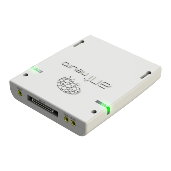
For details refer to the dedicated datasheet. Figure 2-1. The eego amplifier EE-430 shown from the front. A high-density 50 pin connector (EEG IN) provides access to 8 shielded input channels, reference and ground. TTL trigger signals can be Trigger input ports “TR IN 1” and “TR IN 2”. Four mechanical through holes in the amplifier housing allow securing the amplifier, e.g. - Page 10 EE-41x EE-43x User Manual Figure 2-2. The eego amplifier EE-430 shown from the rear. The USB3 micro connector provides access to control the hardware and to stream data. It also powers the device. Figure 2-3. The LED status indicator light bars are both showing the status of the eego amplifier EE-430.
- Page 11 EE-41x EE-43x User Manual Figure 2-4. The product label at the bottom of the amplifier device shows manufacturer information, product name, code and revision, and serial number, year of production and CE marking. The symbols in the bottom row points are explained in Appendix C.
- Page 12 EE-41x EE-43x User Manual Figure 2-6: XS-432 trigger port adapter (connects to TR IN 1 and TR IN 2). Refer to dedicated datasheet for XS-432 for pinning information. Figure 2-7: Connection diagram. Rev. 2.6, DRN-PDO-1558d 12 of 21...
-
Page 13: Biosignal And Impedance Measurements
With the eego amplifier you can also record bipolar signals. In this case the REF channel is not used but each of the 8 channels is measuring the difference between its positive and negative input port. -
Page 14: Recording Trigger Input
Low level must also be hold for 2-3 times the reciprocal of the sampling rate. MOUNTING OPTIONS FOR THE EEGO AMPLIFIER The eego amplifier EE-4xx can be used as a stationary device or as a mobile device. When using eego amplifier as a stationary device, please make absolutely sure that the amplifier cannot drop from the table, e.g. -
Page 15: Led Status Indicator Lights For The Eego Amplifier Ee-4Xx
LED STATUS INDICATOR LIGHTS FOR THE EEGO AMPLIFIER EE-4XX The LED lights at the side edges of the eego amplifier EE-4xx (refer to Figure 2-3) indicate power and data status as well as possible hardware problems. The two multi-color LED indicators at each side operate symmetrically (identical signaling). -
Page 16: Appendix A: Connectors And Pinning Tables
APPENDIX A: CONNECTORS AND PINNING TABLES EEG CONNECTOR The eego amplifier EE-4xx has one EEG input connector labeled “EEG IN”. The 50-pin high-density, high-quality connector give access to the 8 shielded referential inputs (EE-411, EE-430) or bipolar inputs (EE-410), the reference electrode and the patient ground. The table below provides the mapping between connector pins, channel numbers and electrode labels when combined with a CA- 411 waveguard cap. -
Page 17: Trigger Connectors
The third trigger port “TR OUT” is reserved and must remain open. Do not connect to it. POWER AND DATA TRANSMISSION VIA USB CONNECTOR The micro USB 3 connector of the eego amplifier must be connected with a USB 2.0 compatible port of a compatible computer (refer to APPENDIX D: Datasheet). -
Page 18: Appendix B: Amplifier Technical Specifications (Emc)
Guidance and manufacturer’s declaration – electromagnetic emissions The eego amplifier EE-430 is intended for use in the electromagnetic environment specified below. The customer and/or user of the eego amplifier EE-430 should ensure that it is used in such an environment. -
Page 19: Appendix C: Explanation Of Symbols
EE-41x EE-43x User Manual APPENDIX C: EXPLANATION OF SYMBOLS Manufacturer symbol: indicated with name, address Serial number Year of manufacture Conformité Europeenne, CE mark, with number of Notified Body involved in the conformity assessment Follow the instructions for use (i.e., this user manual) -
Page 20: Appendix D: Datasheet
Classification: CE class IIa according to the MDD 93/42/EEC Annex IX Description: The eego amplifier has been designed as a mobile recording device for EEG signals. It provides access to recorded data over a USB connection to external software over its signal driver interface. - Page 21 Warning: Proper use of the eego amplifier depends on careful reading of all instructions and labels that come with or are present on the device. Incorrect use of the device may cause inaccurate measurements. Non-compliance with warnings and safety regulations may result in severe personal injury and total loss of equipment.
Need help?
Do you have a question about the EE-41 Series and is the answer not in the manual?
Questions and answers