
Subscribe to Our Youtube Channel
Related Manuals for PUSR USR-DR13 Series


Summary of Contents for PUSR USR-DR13 Series
- Page 1 USR-DR13X User Manual Serial to Ethernet User Manual USR-DR132/DR134 V2.0 Be Honest & Do Best Your Trustworthy Smart Industrial IoT Partner pusr.com...
-
Page 2: Table Of Contents
3.2.2. Parameter settings ........................- 23 - 3.2.3. Open web server ........................- 24 - 3.2.4. Firmware upgrade ........................- 25 - 3.2.5. Restart the device ........................- 25 - 3.2.6. Restore to factory default settings ....................- 26 - pusr.com - 2 -... - Page 3 6. Additional features ............................- 42 - 6.1. Index function ............................- 42 - 7. Warranty ................................- 44 - 8. Contact Us ..............................- 44 - 9. Disclaimer ..............................- 44 - 10. Revision History ............................- 45 - pusr.com - 3 -...
-
Page 4: Introduction
1. Introduction 1.1. Overview USR-DR13X is an ultra-small DIN rail mounting industrial-grade serial device server launched by PUSR. It can realize two-way fast data transmission between RS232/RS485 and RJ45 Ethernet port. It integrates TCP/IP protocol stack internally and Modbus gateway function. It can be directly integrated into industry scenarios, thus quickly completing business framework construction and saving human resources investment. -
Page 5: Get Started
Terminal wiring definitions are shown below. Table 2. Pin description Type Description DC 5-24V + Positive input of the power supply DC 5-24V - Negative input of the power supply RX/A Serial signal TX/B Serial signal pusr.com - 5 -... -
Page 6: Ethernet Port
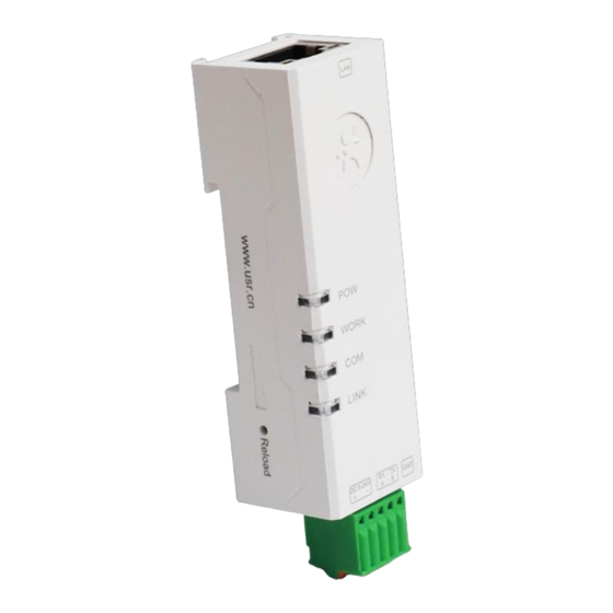
There are 4 indicators on the device: POW, WORK, COM, LINK. The LED indicators description is in the following table. Table 4. LED indicators description LED name Status Description Power supply is normal Power(Red) No power supply or abnormal power supply Work(Green) Blinking(Slow) System is booted up and running pusr.com - 6 -... -
Page 7: Reset To Factory Setting
For specific function details and instructions, please refer to the subsequent chapters. 2.2.1. Download software Download the software from PUSR’s website: pusr.com - 7 -... - Page 8 USR-DR13X User Manual https://www.pusr.com/support/download/Setup-Software-USR-M0-V2-2-6-1- Config software: exe.html https://www.pusr.com/support/download/usr-tcp232-test-V13.html Test software: After downloading, run the config software. It is strongly recommended for the users to set the Network Parameters through configuration tool first. Other device-specific configurations can later be carried out via user-friendly Web-Interface.
-
Page 9: Hardware Connection
1.Users can search out the DR13X device, 2.Set the IP type as DHCP/Auto IP, 3.Save config, 4.Search the device again, 5.Open the webpage, the user will be navigated to the login page, the username and password are both “admin”. pusr.com - 9 -... - Page 10 After entering the username and password, click "OK" and the server will authenticate. After success, you will enter the main page of the Web server, as shown in the following figure. Figure 7. Current status In serial port page, set the remote IP to 192.168.1.182, then save parameters and restart the module. pusr.com - 10 -...
- Page 11 192.168.0.7. Set the PC's IP address as: 192.168.0.X (X is any valid value from 2 to 253 except 7). The specific Windows system operation page is shown in the following figure. you can access the Web page of the USR- DR13X series serial server through browser as mentioned above. pusr.com - 11 -...
-
Page 12: Data Transmission Test
In this test, we use the default serial port parameters (115200, N, 8, 1) to test. Users can also to modify the baud rate, data bit and other parameters of the serial port via webpage or config software as needed. The following picture shows an example of parameters setting to test transparent transmission. pusr.com - 12 -... -
Page 13: Technical Support And Assistance
Please visit the USR IoT website: https://www.pusr.com where you can find the latest information about the product. Contact your distributor, sales representative, or PUSR's support center: http://h.usriot.com/index.php?c=frontTicket&m=sign for technical support if you need additional assistance. Please have the following information ready before you submit a ticket: –... -
Page 14: Status
Figure 15 illustrates the status page of the web interface. pusr.com - 14 -... - Page 15 IP:The IP of remote host, it displayed once the TCP connection is established, Tx: The data count from serial to network Rx: The data count from network to serial When the TCO232-30X work in TCP server mode, the page can display up to 5 connection information. pusr.com - 15 -...
-
Page 16: Ip Settings
Class A, B, and C addresses are unicast addresses, Class D addresses are multicast addresses, Class E addresses are reserved addresses for future special purposes. The IP addresses currently in large numbers belong to three types of addresses: A, B, and C. pusr.com - 16 -... -
Page 17: Serial Port Settings
IP packet. All packets whose destination is not in the router's routing table will use the default route. The IP address of the DNS server. When users need to access information online through domain name, like www.pusr.com. DNS translates domain names to so browsers can load Internet resources. - Page 18 Stop bits This indicates that a character has been transmitted. Set this to match the stop bit setting of the connected device. Choices are: 1 and 2. Default is 1 (which is the default pusr.com - 18 -...
-
Page 19: General Settings
3.1.4. General settings USR-DR13X series provide rich additional function which is displayed in this function tab page. The function detail information will be described in the following table, some more important function is introduced in relevant chapters. pusr.com - 19 -... - Page 20 It’s available in TCP client and UDP client mode. Users can identify different MAC: The content of the register packet is the MAC address of DR13X, Customize: User can define the content of the register packet by themselves, USR Cloud: This is used for registering to USR cloud. pusr.com - 20 -...
-
Page 21: System Parameters
DR13X. This function need be used with USR-VCOM software. Index See more information in Chapter 5 3.1.5. System parameters This configuration tab includes several system level settings, such as device name, system log, username, and password. Most of these settings are optional. pusr.com - 21 -... - Page 22 When the length of data received by serial port reaches the set value, it is sent as a packet. The default is 400 bytes, and the range is 1~1024 bytes. No data restart This function is used for the serial device server without any data transmission or pusr.com - 22 -...
-
Page 23: Configuration Software
Serial Device Server List Area of the utility. Figure 18. Search device 3.2.2. Parameter settings Users can modify the parameters as needed, and the click “Save Config” to make the parameters take effect. More parameters can be checked by scrolling down or up. pusr.com - 23 -... -
Page 24: Open Web Server
External web config ,you will open the web server with default browser such as Google Chrome. 1.Right-click a desired device to display the settings menu, 2.Select OpenWeb pusr.com - 24 -... -
Page 25: Firmware Upgrade
This function is available to allow you to reset the serial device server. The function disconnects both the ethernet and serial connections. The function also allows the serial device server to save new configuration settings to flash memory. To reset the device: 5.Right-click a desired device to display the settings menu, 6.Select Restart pusr.com - 25 -... -
Page 26: Restore To Factory Default Settings
1.Right-click a desired device to display the settings menu, 2.Select Reset Figure 23. Restore to factory default settings pusr.com - 26 -... -
Page 27: Operation Mode
Setting of the software is shown in the following picture. Once the TCP connection is established, the link indicator will turn on. Protocol: TCP Client Remote Host Address: 192.168.1.184 (the IP of USR-DR134) Remote Host Port: 503 (the local port of USR-DR134) The data transmission is shown in Figure 25. pusr.com - 27 -... -
Page 28: Tcp Client
4.2. TCP client When the work mode is TCP client, the remote device must work in TCP server mode. The USR-DR13X will initiate the TCP connection and the remote server IP and port should be configured. pusr.com - 28 -... - Page 29 USR-DR134. After the connection is established, we can see the IP and port of USR-TCP232-306, as shown in the red box of the following picture. Figure 27. Setting of USR device and test software pusr.com - 29 -...
-
Page 30: Udp Server
IP and port are changed to the one which send the UDP data to USR-TCP232-306. Figure 29. UDP server mode For test software, 1.The local host port is the same with the remote port of the USR-TCP232-306, pusr.com - 30 -... - Page 31 There is another condition, the local host port is not the same with the remote port of the USR-TCP232-306. If so, the network test software must send the first data packet to USR-DR13X(work as UDP server). pusr.com - 31 -...
-
Page 32: Udp Client
Figure 34. Test result with data transmission 4.4. UDP client 4.4.1. Transparent data transmission In UDP client mode, DR13X will only communicate with target IP/Port. If data is not from target IP/Port, it won’t be received by DR13X. pusr.com - 32 -... - Page 33 USR-DR13X User Manual Figure 35. UDP client Figure 36. Test result of UDP client pusr.com - 33 -...
-
Page 34: Udp Data Filtering
If the target IP is host IP like 192.168.1.182: USR-DR 13X determines whether the data source port and IP are the same as the target port and IP of DR 13X. If the data is the same, the data is output from the serial port, otherwise the data is discarded. Figure 37. Settings of UDP broadcast pusr.com - 34 -... -
Page 35: Http Client
The http connection of DR13X is short connection, if the device does not receive the data sent by the serial port device after waiting for the pre-set time, it will actively disconnect. The default pre-set time is 3 second. Figure 38. Settings of Httpd client pusr.com - 35 -... -
Page 36: Modbus Gateway
USR-DR13X User Manual Figure 39. Test result of httpd client 5. Modbus Gateway After enabled the Modbus gateway, users can achieve Modbus TCP/RTU conversion, data reporting in Json format and etc. 5.1. Modbus Parameter details pusr.com - 36 -... -
Page 37: Modbus Rtu/Tcp Conversion
Range: 1~65525ms Abnormal Response Open: Send abnormal response to network end Open Close: Not send abnormal response to network end 5.2. Modbus RTU/TCP conversion The USR-DR13X series support Modbus protocol conversion. pusr.com - 37 -... -
Page 38: Modbus Poll Function
The modbus poll function only supports the setting of complete Modbus RTU commands, and a maximum of 5 acquisition commands can be set. Each command can have a maximum of 16 bytes. The acquisition commands can be set through AT commands, and the command setting format is: pusr.com - 38 -... - Page 39 Reporting Protocol: It can be selected as Modbus RTU transparent transmission reporting or Json reporting. The Json data format is as follows: "id":"Device MAC", "cmd":"Modubs query command", "rsp":"Modbus response data" Figure 42. Modbus poll function Figure 43. Parameters setting pusr.com - 39 -...
-
Page 40: Abnormal Response
5.4. Abnormal Response If DR13X fails to receive a Modbus response data from the serial device within the set time limit or the Modbus response data is incorrect, it will report an abnormal response to the network-end device. pusr.com - 40 -... - Page 41 USR-DR13X User Manual Figure 46. The abnormal response of Modbus poll function pusr.com - 41 -...
-
Page 42: Additional Features
The Index function is mainly to solve the problem that in the TCP Server mode, when the user has multiple clients connected to the 30X and sends and receives data at the same time, the data source cannot be distinguished or cannot be sent to a specific client. pusr.com - 42 -... - Page 43 When the serial device needs to send data to a specific client, such as sending data to the first client, you can add O1 in front of the data, such as we send O1www.usr.cn meaning sending www.pusr.com to the first clients.
-
Page 44: Warranty
8. Contact Us Jinan USR IOT Technology Limited Address : Floor 12 and 13, CEIBS Alumni Industrial Building, No. 3 Road of Maolingshan, Lixia District, Jinan, Shandong, China Official website:https://www.pusr.com Official shop:https://shop.usriot.com Technical support: http://h.usriot.com/ Email : sales@usriot.com Tel : +86-531-88826739 Fax : +86-531-88826739-808 9. -
Page 45: Revision History
USR IoT and/or its affiliates do not make any commitment to update the information contained in this document. 10. Revision History Version Date Author Description V1.0.3.01 2017-09-20 Established V1.0.4 2023-07-03 May Liu 1. Add description of Modbus Gateway 2. Add description of Multicast pusr.com - 45 -... - Page 46 USR-DR13X User Manual Official Website: www.pusr.com Official Shop: shop.usriot.com Technical Support: h.usriot.com Inquiry Email: inquiry@usriot.com Skype & WhatsApp: +86 13405313834 关注有人微信公众号 登录商城快速下单 Product Catalog Facebook Youtube Click to view more: & & pusr.com...
Need help?
Do you have a question about the USR-DR13 Series and is the answer not in the manual?
Questions and answers