Table of Contents
Advertisement
Quick Links
SIGMA AUTOMATICS SA300
Operation & Installation Manual
LOW ENERGY AUTOMATIC SWING DOOR OPERATOR
These installation instructions are solely for use by professional
installers and are not intended to be handed over to the end user.
SIGMA AUTOMATICS
6795 Steels Ave W, Etobicoke, ON M9V4
T 416-746-6100
www.sigmaautomatics.com
Advertisement
Table of Contents

Subscribe to Our Youtube Channel
Related Manuals for Sigma AUTOMATICS SA300

Summary of Contents for Sigma AUTOMATICS SA300
- Page 1 SIGMA AUTOMATICS SA300 Operation & Installation Manual LOW ENERGY AUTOMATIC SWING DOOR OPERATOR These installation instructions are solely for use by professional installers and are not intended to be handed over to the end user. SIGMA AUTOMATICS 6795 Steels Ave W, Etobicoke, ON M9V4 T 416-746-6100 www.sigmaautomatics.com...
- Page 2 Failure to follow the instructions and information in this manual may result in personal injury or damage to equipment. SIGMA AUTOMATICS will not be held responsible for any loss, damage or injury if instructions and proper precautions are not followed. To reduce the risk of injury or damage - use this operator with single or double pedestrian swinging doors only.
-
Page 3: Table Of Contents
SA300 Installation Instructions Table of Contents 1. Product Summary ............................... 4 1.1. Product Specifications / Technical Data....................... 4 2. Pre-Installation Information ............................5 2.1. Parts list ................................5 2.2. Required Tools ..............................6 2.3. Fasteners ................................6 2.3.1. Torque Ranges .............................. 6 3. - Page 4 SA300 Installation Instructions 6.5. Manual Programming Encoder and Parameters (HD MODEL) ................26 6.6. Password Menu – Set Password ........................28 6.7. Password Menu – Clear Password ........................28 7. Motor Hand Swap ..............................29 8. Troubleshooting ............................... 30 9. Safety Signage and Access Control Placement ......................31 9.1.
-
Page 5: Product Summary
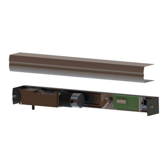
The SIGMA SA300 door operator is installed onsite by qualified or trained installers. Header unit (or main unit) must be installed on the interior of a building. For double swing doors (IE: SA320, SA350), both operators are installed in one single header. -
Page 6: Pre-Installation Information
SA300 Installation Instructions 2. Pre-Installation Information 2.1. Parts list Before installation, please verify that the product was shipped with all required components. Verify the model number, header width, door handing, arm and colour. • Do not attempt installation if any parts are missing. •... -
Page 7: Required Tools
SA300 Installation Instructions 2.2. Required Tools 1- 1/8 Allen key 2- 1/4 Allen key 3- 3/16 Allen key 4- 5/64 Allen key 5- 0.3 mm Flat head screwdriver 6- 9/16 Wrench 7- #3 Phillips Screwdriver 8- Torque wrench 9- Door pressure gauge (0-35 lbf). 10- Various drill bits and fasteners (see section 2.3) Figure 2-2 Required Tools... -
Page 8: Safety Information
SA300 Installation Instructions 3. Safety Information This document contains important instructions for installation of the SA 300 swing door operators. Review these instructions thoroughly prior to installation and follow them carefully during installation, commissioning, troubleshooting and maintenance. 3.1. Safety Warnings •... -
Page 9: Sa300 Installation Process
SA300 Installation Instructions 4. SA300 Installation Process • Unpack and remove cover. • Remove components. Step 1 • Mount back plate. Step 2 • Reinstall components. Step 3 • Arm adjustment and installation. Step 4 • Program,Learn the door operator. Step 5 •... -
Page 10: Unpack And Remove Cover
SA300 Installation Instructions 4.1. Unpack and Remove Cover • Use 1/8" Allen key to remove cover screws. • Remove cover. • Verify operator handing. Left Hand Push show below (Figure 4-1). Figure 4-1 Left Hand Push Model 4.1.1. Operator Handing Left Hand Right Hand PULL:... -
Page 11: Mount Header Unit
SA300 Installation Instructions 4.2. Mount back plate NOTE: Installers should use their discretion when mounting the header unit. They should ensure that the door operator is properly and securely mounted using appropriate fasteners and mounting methods. • Mark the positions of the gearbox and controller mounting plates edges on the rear plate channel of the header. -
Page 12: Reinstall Components
SA300 Installation Instructions Push application 1 ½ in flush with bottom of frame. Pull application 2” Hinge from top of the door Centerline Figure 4-4 Header Unit Position (Pull Application) • After the header’s position is determined, BEFORE physical mounting, ensure that a hole for the wire pass-through is made on the header that corresponds with the wire hole on the surface. -
Page 13: Installation Examples
SA300 Installation Instructions 4.3. Installation Examples • Ensure there is solid structural support in the mounting surface (wall) behind the header unit for the appropriate mounting hardware to be secured to. • A spacer or filler plate made of solid material may be required to compensate for any gap between the door frame/header unit and mounting surface. -
Page 14: Motor And Control Board Wiring
SA300 Installation Instructions 4.4. Motor and Control Board Wiring Unit must be grounded. Connect 120VAC wire to transformer via L16 connector and distribution block. Use Minimum of No. 14 AWG with copper connectors. Permanent wiring is to be employed as required by local codes. •... -
Page 15: Arm Installation
SA300 Installation Instructions 4.5. Arm Installation SA300 arms can be installed in either a PUSH or PULL configuration. Regardless of configuration, the gearbox must be loaded to hard stop. 4.5.1.1. Automatic Gearbox Loading to Hard Stop • Turn POWER ON. Screen will display 2 options as in image above. •... -
Page 16: Push Arm Installation
SA300 Installation Instructions 1/2" hole to lock gearbox Door Frame ~45° Operator Door Figure 4-8 Push Arm Positioning 4.5.2. PUSH Arm Installation • Attach or re-adjust the push arm to be approximately 45° from parallel to the door frame as shown in Figure 4-8. -
Page 17: Pull Arm Installation
SA300 Installation Instructions 4.5.3. PULL Arm Installation • With the door closed, install main arm and mark the location of the main arm’s tip on the closed door (A). • Remove the arm and open the door to the desired opening angle and hold it in place. Re-attach main arm and mark the location of the main arm’s tip on the open door (B). -
Page 18: Terminal Wiring
SA300 Installation Instructions 5. Terminal Wiring 5.1. Terminal Description / Legend Lock relay used for operating electric locking hardware. 24VDC power terminal used to power device and looking hardware. Shared input for all dry device and as 0VDC output for power devices. RLY 1 is used: in Normal Mode as end switch when input is maintained to ACT2 and common;... -
Page 19: Wiring Example: Regular Push-Button Activation
SA300 Installation Instructions 5.2. Wiring Example: Regular Push-Button Activation The following diagram is only an example, use only as a reference. Electric Strike (Fail-Secure) Exterior Push Button Interior Push Button REV.2023-10-01 18 / 32... -
Page 20: Wiring Example: Card Access Integration
SA300 Installation Instructions 5.3. Wiring Example: Card Access Integration The following diagram is only an example, use only as a reference. Electric Strike (Fail-Secure) After the initial auto-learning sequence is complete (see 6.2), use the control board menu to set the Exterior Control Mode to 3 “Access Push Button... -
Page 21: Wiring Example: Washroom Application
SA300 Installation Instructions 5.4. Wiring Example: Washroom Application The following diagram is only an example, use only as a reference. REV.2023-10-01 20 / 32... -
Page 22: Wiring Example: Stairwell (Fire-Alarm) Application
SA300 Installation Instructions 5.5. Wiring Example: Stairwell (Fire-Alarm) Application The following diagram is only an example, use only as a reference. Electric Strike (1.2Amps max.) > FAIL-SAFE DETERMINED BY LOCATION AND LOCAL FAIL-SECURE CODES. PLEASE CONSULT LOCAL AUTHORITY. N/C To Pressure Fan (Output) FIRE FIRE ALARM... -
Page 23: Programming
SA300 Installation Instructions 6.3. Change Operating Parameter Settings The SA300 default operating parameter settings can be adjusted to better suit the installation. See Section 6.3.2 for a full list of basic and advanced parameters. • Ensure the door is fully closed – the door operator control display should read “DOOR CLOSED.” •... -
Page 24: Basic Programming (Initial Auto-Learning)
SA300 Installation Instructions 6.3.2. Parameter Descriptions All values and settings must comply with ANSI/BHMA A156.19 Standard for Power Assist and Low Energy Power Operated Swing Doors Parameter Description Value Default Percentage of current that the door operator will use to reverse 0-99 Overload if an obstacle is detected during the Opening Cycle. -
Page 25: Universal Washroom Mode
SA300 Installation Instructions 6.3.3. Recommended Parameter Settings by Door Size All values and settings must comply with ANSI/BHMA A156.19 Standard for Power Assist and Low Energy Power Operated Swing Doors. Parameter For 7ft to 8ft Door For 8ft to 12ft Door Overload 70-85 75-90... -
Page 26: Calibration Menu (Force Re-Learn)
SA300 Installation Instructions 6.3.5. Access Control Mode • Press the MENU button on the control Board to enter the Programming Menu. • Install the door operator for required application based on installation instructions. • Adjust parameters for basic setup. (As per 6.3.3) •... -
Page 27: Manual Programming Encoder And Parameters (Hd Model)
6.5. Password Menu – Set Password WARNING: Use this function with caution. Recovering from a lost password will require a direct service call to Sigma Automatics. • Ensure the door is fully closed – the door operator control display should read “DOOR CLOSED.”... - Page 28 SA300 Installation Instructions • Press the SEL button to enter the PASSWORD menu. PASSWORD [Set] • Using the UP and DN buttons, scroll up or down until “[Set]” is displayed. • Press the SEL button to begin setting your PASSWORD. SET PASSWORD 1 2 3 4 >...
-
Page 29: Password Menu - Set Password
SA300 Installation Instructions 6.6. Password Menu – Clear Password • Ensure the door is fully closed – the door operator control display should read “DOOR CLOSED.” • Press the MENU button on the control board to enter the Main Menu. User will be prompted to enter the password. -
Page 30: Motor Hand Swap
SA300 Installation Instructions 7. Motor Hand Swap Step 1: Take out the 3 mounting screws. Right Hand configuration image should be mirrored Step 2: Take out the shaft mounting screw on top of the gearbox and disengage the shaft from the Step 3: Flip the gearbox 180°... -
Page 31: Troubleshooting
SA300 Installation Instructions 8. Troubleshooting Problem Possible Solutions • Verify power connection. • Verify ON/OFF switch is set to ON. • Verify the connection of activation devices Door does not open and/or sensors. • Verify the display message. • Verify position value 100. Display does not indicate door closed •... -
Page 32: Safety Signage And Access Control Placement
SA300 Installation Instructions 9. Safety Signage and Access Control Placement • Always apply supplied stickers on both sides of the door at locations stipulated by local codes. • See ANSI standard A156.19 requirements for additional safety decal information • Safety signage included with SA300 are double-sided labels intended for application on clear glass. A second set of labels will be required if labels are applied on an opaque or non-transparent surface. -
Page 33: Sa320 Surface Mounted Paired Operator (Auto/Auto - Double Auto)
SA300 Installation Instructions Appendix 1: Other Device Configurations 10.1. bSA320 Surface Mounted Paired Operator (Auto/Auto – Double Auto) Parts list for a surface mounted header, paired operators and regular arm kits. Description Part Number Operator cover and screws SA-PH-001 Operator motor and gearbox x2 SA-PM01 (motor) SA-PG01 (gearbox) Operator control board and transformer x2... -
Page 34: Appendix 2: Safety Check List
SA300 Installation Instructions 11. Appendix 2: Safety Check List This checklist is provided to help ensure pedestrian safety and the proper operation of the door operator. These safety checks are repeated on the AAADM sticker applied to the door frame. •...
Need help?
Do you have a question about the AUTOMATICS SA300 and is the answer not in the manual?
Questions and answers
I installed a Sa300 but when i turned it On, didn’t display 2 Options but went straight to saying opening door. So long story short , it won’t let me perform the learning cycle, it just opens the door and then stays closed
The Sigma AUTOMATICS SA300 goes straight to "opening door" and does not display the options for the learning cycle likely because the door is not fully closed or there are obstacles in the doorway. According to the instructions, the door must be fully closed and free of obstacles before turning the power on for the learning cycle.
This answer is automatically generated
door operated maybe 10 times properly, then slammed shut and now say door closed error and will not operate