Table of Contents
Advertisement
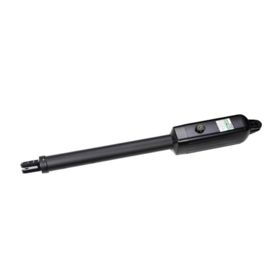
Swing Gate Opener
User's Manual
Model:
RX1102
RX1101
★ Please read and follow all warnings, precautions and
instructions before
installation and use.
★ Never connect the solar panel to the control board directly to charge the battery.
★ Periodic checks of the opener are required to ensure safe operation.
★ Save this manual.
Advertisement
Table of Contents

Related Manuals for RITROX RX1102

Summary of Contents for RITROX RX1102
- Page 1 Swing Gate Opener User’s Manual Model: RX1102 RX1101 ★ Please read and follow all warnings, precautions and instructions before installation and use. ★ Never connect the solar panel to the control board directly to charge the battery. ★ Periodic checks of the opener are required to ensure safe operation.
-
Page 2: Table Of Contents
Table of Contents Safety Installation Information .......................... 1 Single Gate Opener Parts List ......................... 2 Optional Accessories Parts List........................2 Tools Needed: ..............................2 Technical Specifications & Features ........................ 3 Single Gate Overview............................6 Preparation for Installation ..........................6 Install the Gate Opener on the Gate ........................ 7 Mounting of the Control Box ..........................11 Connection of the Power Supply ........................ -
Page 3: Safety Installation Information
on any pedestrian gate. Pedestrians must be supplied Safety Installation Information with a separate pedestrian access. 1. READ and FOLLOW all instruction. For an installation utilizing non-contact sensors The gate opener is intended for use with Class I (safety sensors), see product manual on the placement vehicular swing gates. -
Page 4: Single Gate Opener Parts List
13. To AVOID damaging gas, power, or other SAVE INSTRUCTION. underground utility lines, contact underground utility 14. Do not permit children to play on or around the gate locating companies BEFORE digging. and keep all controls out of their reach. Single Gate Opener Parts List... -
Page 5: Optional Accessories Parts List
Optional Accessories Parts List Tools Needed: ·Power Drill ·Tape Measure ·Open End Wrenches - 14# &17# or Adjustable Wrenches ·Wire Strippers ·C-Clamps - small, medium, and large ·Level ·Hacksaw or Heavy Duty Bolt Cutters ·Phillips Screwdriver ·An extra person will be helpful... -
Page 6: Technical Specifications & Features
Technical Specifications & Features Specifications Model: RX1101 Input: 110V~120V/60Hz or 220~240V/50Hz Motor voltage: 24VDC Power: 50W each actuator Current: Actuator speed: 16mm/s Max. actuator travel: 385mm Ambient Temperature: -22° ~ 55° (-4°F to 122°F) Protection class: IP44 RX1101 Features: ・Soft start and soft stop ・Emergency release key in case of power failure ・Dual/Single gate running mode ・Adjustable opening/closing interval between master and slave gate... -
Page 7: Single Gate Overview
Single Gate Overview Preparation for Installation There are two installation types for the gate opener, Pull-to-Open and Push-to-Open. In the Push-to-Open installation, gate opens out from the property. A Push-To-Open Bracket (PSO part) is required to be used for each gate. NOTE: Ensure the gate does not open into public areas. -
Page 8: Install The Gate Opener On The Gate
Install the Gate Opener on the Gate The position of Post Bracket is very important. The following illustrations and tables are required to determine the proper mounting position for the Post Bracket. The tables show the maximum opening angle of the gate for a given A and B. - Page 9 Push-to-Open Installation — Gate in Closed position (Moving-Rod is retracted) 1. Insert the M10 x 30 bolt through the center hole of the post bracket and post pivot bracket as shown. Place a ¢10 washer , ¢10 lock washer and M10 nut on the bottom of the bolt and hand tighten.
- Page 10 5. Make sure that there is a minimum clearance of 2.5cm between the gate and the opener and that the opener and the Post Pivot Bracket are not binding in both the gate-open and gate-closed positions. If there is not at least 2.5cm of clearance or if the opener and the Post Pivot Bracket are binding, rotate the Post Pivot Bracket and/or move the Post Bracket Assembly to obtain the minimum clearance and eliminate the binding.
- Page 11 6. Sign the bolt-hole point on the gate bracket and gate. Do this by placing a punch or a sign in the middle of each bolt slot on the post bracket assemblies and the gate bracket. It allows slight adjustments to the post bracket. Then remove the post bracket and gate bracket by taking off the C-clamps.
-
Page 12: Mounting Of The Control Box
10. Cut off any part of the bolts that extend beyond the tightened nuts. 11. With the gate opener fully retracted and with the gate in the fully open position (for Pull-to-Open installation) or fully closed position (for Push-to-Open installation), attach the gate opener to the Post Bracket Assembly and the Gate Bracket by inserting a clevis pin through the gate opener and the Post Pivot Bracket and another clevis pin through the gate opener and the Gate Bracket. -
Page 13: Connection Of The Power Supply
CAUTION: Install the Control Box in a well ventilated place protected against rain and sunlight. 3.Insert the cable of the second gate opener and alarm lamp cables into the control box through middle strain relief. Then repeat step 2. 4. Insert other cables into the control box through rightmost strain relief. Then repeat step NOTE: Only motor cables (1.5m length) are provided. -
Page 14: Connection Of The Control Board
Connection of the Control Board... -
Page 15: Motor Connection For Pull-To-Open
Motor connection for PULL-TO-OPEN Actuator 1 Insert the stripped cable wires into the appropriate terminals on the opener terminals block. The red wire should be inserted into the “MOTOR1+” terminal, the black wire into “MOTOR1-“, the blue wire into ULT1, the green wire into COM, and the yellow wire into DLT1 terminal. -
Page 16: How To Learn Or Erase The Remote
First insert the LOOP DETECTOR BOARD into the CONTROL BOARD, and then connect the LOOP DETECTOR to the control board. Detailed instruction please refers to the manual instruction of LOOP DETECTOR separated. Exit Wand (optional) Please refers to the manual instruction of EXIT WAND separated. Electric Lock (optional) The electric lock should be wired to the “LOCK”... -
Page 17: Setting Of The Control Board
Setting of the Control Board 1. Check again for completed and correct assembly of your swing gate opener and gate. Plug the Power Grounded Cord into the nearest AC outlet. The Digital Display on the Control Board will flash with “- -”. The unit is in standby. 2. - Page 18 Without a properly installed safety reversal system, person (particularly small children) could be SERIOUSLY INJURED or KILLED by a closing gate. *Too much force on gate will interfere with proper operation of safety reversal system. *NEVER increase force beyond minimum amount required to close gate. *NEVER use force adjustments to compensate for a binding or sticking gate.
-
Page 19: Indicate Illustration On The Digital Display When Gate Opener Is Running
indicates “11”, the PBS is available. The Digital Display indicates “00”, the PBS is null. Note: If the “11” is be set, the gate opener won’t work until the PBS system is equipped. The PBS system works only when gate opener is closing. The gate opener will return to its open position when the obstruction blocks the beam from photo eye. -
Page 20: Adjusting The Limit Switch
Adjusting the Limit Switch The position of Limit Switch A was fixed in factory, do not adjust it again. Plug on the power to running gate opener, use a screwdriver to loose the screw of Limit Switch B, slide Limit Switch B to the desired closed position and fix it. -
Page 21: Trouble Shooting
Trouble Shooting 1. Opener does not run. Digital Display indicator is not on. • Check if all motor are properly connected and color coded. Make sure the AC input is connected. • Check if the fuse in control board is bad. 2. -
Page 22: Quick-Setting Guide
Quick-Setting Guide... - Page 26 ©2021-2024 All Rights Reserved...
Need help?
Do you have a question about the RX1102 and is the answer not in the manual?
Questions and answers
We have a single arm solar gate, but instructions are for a double do we have to connect it as a double, totally confuse, or can you recommend any one to connect it for us here in Perth WA.
For a RITROX RX1102 single arm solar gate, follow the same instructions as for a double arm but only connect one motor. Insert the power cable and the single gate opener cable through the front strain relief into the control box. Connect only one motor cable to the appropriate motor terminal on the control board. Do not connect the second motor terminals. Ensure all other steps—such as power supply, control board connections, and accessories—are followed as described.
This answer is automatically generated