Fujitsu AirStage AGUA7TLAV1 Installation Manual
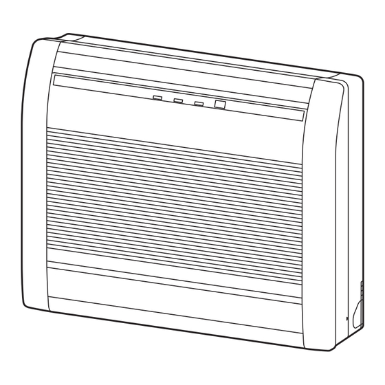
Indoor unit (floor type)
Hide thumbs
Also See for AirStage AGUA7TLAV1:
- Design & technical manual (978 pages) ,
- Operating manual (8 pages)
Table of Contents
Advertisement
Quick Links
TM
INSTALLATION MANUAL
INDOOR UNIT (Floor type)
For authorized service personnel only.
MANUEL D'INSTALLATION
UNITÉ INTÉRIEURE (Type sol)
Pour le personnel agréé uniquement.
MANUAL DE INSTALACIÓN
UNIDAD INTERIOR (Tipo suelo)
Únicamente para personal de servicio autorizado.
AGUA4TLAV1
AGUA7TLAV1
AGUA9TLAV1
AGUA12TLAV1
AGUA14TLAV1
PART No. 9382568030-02
Advertisement
Table of Contents

Related Manuals for Fujitsu AirStage AGUA7TLAV1


Summary of Contents for Fujitsu AirStage AGUA7TLAV1
- Page 1 INSTALLATION MANUAL INDOOR UNIT (Floor type) For authorized service personnel only. MANUEL D’INSTALLATION UNITÉ INTÉRIEURE (Type sol) Pour le personnel agréé uniquement. MANUAL DE INSTALACIÓN UNIDAD INTERIOR (Tipo suelo) Únicamente para personal de servicio autorizado. AGUA4TLAV1 AGUA7TLAV1 AGUA9TLAV1 AGUA12TLAV1 AGUA14TLAV1 PART No.
-
Page 2: Table Of Contents
INSTALLATION MANUAL 1.2. SPECIAL PRECAUTIONS PART No. 9382568030-02 VRF system indoor unit (Floor type) When Wiring Contents ELECTRICAL SHOCK CAN CAUSE SEVERE PERSONAL INJURY OR DEATH. ONLY A QUALIFIED, EXPERIENCED ELECTRICIAN SHOULD ATTEMPT TO WIRE THIS SYSTEM. SAFETY PRECAUTIONS ................... 1 •... -
Page 3: About This Product
R410A use. Because the pressure of R410A refrigerant is approximately 1.6 times higher than the R22, failure to use All Fujitsu General products are manufactured to metric units and tolerances. United dedicated piping material or improper installation can cause rupture or injury. -
Page 4: Installation Dimension
3.4. Side panel L, R removal and installation 3.2. Installation dimension Unit: in (mm) The intake grille removal 4 (100) or more (1) Open the intake grille. 4 (80) or (2) Remove the rope. more (3) Lay down the intake grille, until the axle at the bottom of the intake grille is removed. The intake grille installation (1) The fixing axle of the intake grille is installed on the Panel. -
Page 5: Indoor Unit Installation
For RIGHT REAR or LEFT REAR piping WARNING (The following figure is a front view of the indoor unit installation location.) Fix the indoor unit with 4 screws surely. If improperly installed, might cause to injury due Unit: in (mm) to the toppling or falling. -
Page 6: Pipe Requirement
4.3.3 Pipe connection 4.2. Pipe requirement When the flare nut is tightened properly by your hand, hold the body side coupling with a separate spanner, then tighten with a torque wrench. CAUTION CAUTION Refer to the installation manual for the outdoor unit for description of allowable pipe Be sure to install the pipe against the port on the indoor unit and the outdoor unit cor- length and height difference. -
Page 7: Electrical Wiring
The drain hose can be connected at either side of the indoor unit. 5. ELECTRICAL WIRING The unit has been shipped with the drain hose connected at left (viewed from the back of the unit) and the drain cap applied at right. WARNING (1) Remove the both side panels. -
Page 8: Wiring Method
A. Current breaker requirements 5.3. Unit wiring • MCA: Minimum Circuit Ampacity MAX. CKT. BKR Model • MAX. CKT. BKR : Maximum Circuit • Before attaching the cable to terminal block. (Fuse capacity) Breaker 5.3.1 Power supply cable AGUA4TLAV1 0.22 A When the power crossover wiring is Conduit connector AGUA7TLAV1... -
Page 9: Wiring
5.3.2 Transmission and Remote controller cable 5.4.2 Transmission and remote controller cable Transmission cable Remote controller cable 1-3/16 in (30 mm) 1-3/16 in (30 mm) Shield cable Push mount cable (no film) 1-9/16 in tie (accessories) (40 mm) • Connect remote controller and transmission cables as shown in figure below. PROHIBITED GOOD Different diameter... -
Page 10: External Input And External Output (Optional Parts)
5.5.2 Connector and DIP switch position Input select Use either one of these types of terminal according to the application. (Both types of CNA01 CNA03 terminals cannot be used simultaneously.) CNA02 CNB01 CNA04 ● Apply voltage terminal ([CNA01], [CNA03]) Controller When a power supply must be provided at the input device you want to connect, use the Apply voltage terminal ([CNA01], [CNA03]). - Page 11 When connected to Dry contact terminals of multiple indoor units with a connected unit, ● Forced thermostat off function insulate each indoor unit with relay, etc. as shown on below example. [“Edge” input only] Connector Input signal Command P.C.B OFF → ON Thermostat off Ch3 of CNA03 or CNA04 ON →...
-
Page 12: Finishing
6. FINISHING 7.1. Side panel L and control cover removal Refer to “3.4. Side panel L, R removal and installation” to remove the side panel L. CAUTION 7.2. Setting the address After checking for gas leaks (refer to the Installation Manual of the outdoor unit), perform this section. -
Page 13: Custom Code Setting
7.3. Custom code setting 00 Enable Enable or disable automatic system restart after a power outage. • Selecting the custom code prevents the indoor unit mix-up. (figure below) Auto restart is an emergency (Up to 4 codes can be set.) function such as for power •... -
Page 14: Test Run
(2) Others Function Function Setting number Default Details number Indication pattern 00 0°F (0°C) Indicator Name Indication pattern 01 1°F (0.5°C) OPERATION indicator lamp (Green) Function number; tens place (0.5s ON/0.5s OFF) 02 2°F (1.0°C) TIMER indicator lamp (Orange) Function number; ones place (0.5s ON/0.5s OFF) Choose the minimum tem- 03 3°F (1.5°C) FILTER indicator lamp (Red) -
Page 15: Error Codes
10. ERROR CODES If you use a wired type remote controller, error codes will appear on the remote controller display. If you use a wireless remote controller, the lamp on the photodetector unit will output error codes by way of blinking patterns. See the lamp blinking patterns and error codes in the table below.
Need help?
Do you have a question about the AirStage AGUA7TLAV1 and is the answer not in the manual?
Questions and answers