Advertisement
Advertisement
Table of Contents

Subscribe to Our Youtube Channel
Related Manuals for Traxxas SLASH BRUSHLESS


Summary of Contents for Traxxas SLASH BRUSHLESS
- Page 1 MODEL 58314-4 ASSEMBLY MANUAL...
-
Page 2: Safety Precautions
• ALWAYS use a Traxxas iD charger to charge Traxxas iD batteries. associated with LiPo battery use. Traxxas does not recommend • DO NOT exceed the maximum manufacturer recommended that anyone under the age of 18 use or handle LiPo battery packs charge rate. - Page 3 SAFETY PRECAUTIONS All of us at Traxxas want you to safely enjoy your new • No Reverse Voltage: The ESC is not protected against model. Operate your model sensibly and with care, and reverse polarity voltage. it will be exciting, safe, and fun for you and those around •...
- Page 4 Thank you for purchasing the Traxxas Slash unassembled kit. parts. Label the paper plates, and then pour the contents The Traxxas Slash short-course race truck puts you in the driver’s of the bags onto them. This puts the parts out in the open seat for intense fender-to-fender, high-flying off-road action.
- Page 5 RADIO SYSTEM INSTRUCTIONS The Traxxas TQ 2.4GHz radio system is provided with your unassembled kit. Complete instructions for operating the radio system are included in the Slash Owner’s Manual. You can download the Owner’s Manual for the Slash, as well as the manuals for all Traxxas vehicles, at Traxxas.com.
-
Page 6: Differential Assembly
A. DIFFERENTIAL ASSEMBLY DIFFERENTIAL BAG A1. Install a sun gear into A2. Assemble planetary gears and install into differential housing differential housing Differential Housing Completed Planetary with Steel Ring Gear 2.5x15.8mm Pin Gear Assembly 2.5x8.8mm Pin Differential Cover Plate Planetary Gear Sun Gear (2) Sun Gear 2.5x8.8mm Pin... -
Page 7: Shock Assembly
B. SHOCK ASSEMBLY SHOCK BAG B1. Assemble front and rear shocks Shock Assemblies Silicone Shock Oil Slowly move piston Front Shock Springs (Short) Fill with to remove excess shock oil air, then let sit a few Rear Shock Springs (Long) minutes until all the Unscrew bubbles are out. - Page 8 C. REAR MODULE ASSEMBLY TRANSMISSION BAG C1. Insert 5x11x4mm bearings into gearbox halves Gearbox Halves (L&R) 5x11x4mm BB 5x11x4mm BB 5x11x4mm BB (4) Note: Bearing Seating Press down hard to ensure bearings are fully seated. Left Gearbox Half Right Gearbox Half TRANSMISSION BAG C2.
- Page 9 C. REAR MODULE ASSEMBLY TRANSMISSION BAG C3. Assemble idler gear shaft and install idler gear shaft assembly into right gear box half 5x11x4mm BB (2) 30T Idler Gear 30T Idler Shaft Assembly Gear Apply drop 5x11x4mm of grease 5x11x4mm 30T Idler Gear Idler Gear Idler Gear Shaft Shaft...
- Page 10 C. REAR MODULE ASSEMBLY TRANSMISSION BAG C6. Install pinion gear onto motor and install motor into transmission case 3x8mm FCS (2) BL-2S Motor Assembly BL-2S Motor Fixed Gear Adapter Assembly 21T Pinion Gear 3x3mm GS Fixed Gear Adapter ELECTRONICS BAG BL-2S Motor 21T Pinion Gear 3x8mm...
- Page 11 C. REAR MODULE ASSEMBLY TRANSMISSION BAG C8. Install gear cover onto transmission case Fold in gear Gear Cover cover tab before installation Gear Cover Plug 3x6mm BCS 3x8mm 3x8mm BCS Gear Cover Plug 3x6mm TRANSMISSION BAG C9. Install inner driveshafts onto transmission case Inner Driveshafts 3x11mm Screw Pin (2) 3x11mm Screw Pin...
- Page 12 C. REAR MODULE ASSEMBLY REAR SUSPENSION BAG C11. Attach the rear shock tower to transmission case 3x12mm BCS (2) 3x12mm BCS Rear Shock Tower Transmission Case REAR SUSPENSION BAG C12. Install rear body post onto rear shock tower Rear Body Mount Rear Body Mount 2.5x12mm CS (4) Rear Shock...
- Page 13 C. REAR MODULE ASSEMBLY REAR SUSPENSION BAG C13. Install rear suspension arms onto transmissions case Rear Suspension Arm (L&R) 3x46mm Screw Pin (2) 3x46mm Rear Suspension Arm Screw Pin (Right) 3x46mm Screw Pin Rear Suspension Arm (Left) REAR SUSPENSION BAG C14.
- Page 14 C. REAR MODULE ASSEMBLY REAR SUSPENSION BAG C15. Install outer driveshaft assemblies 3x31.5mm Screw Pin (2) 3x18mm BCS (2) Correct driveshaft U-joint alignment. 3x18mm Left Outer Driveshaft Assembly 3x18mm Right Outer Driveshaft 3x31.5mm Assembly Screw Pin 3x31.5mm Screw Pin REAR SUSPENSION BAG C16.
- Page 15 C. REAR MODULE ASSEMBLY REAR SUSPENSION BAG C17. Install wheelie bar mount Wheelie Bar Mount 3x40mm BCS 3x30mm 3x40mm Wheelie Bar Mount 3x30mm BCS 3x12mm BCS 3x12mm REAR SUSPENSION BAG C18. Install rear bumper 3x15mm Rear Bumper Rear Bumper Brace Rear Bumper Brace 3x15mm BCS (2)
- Page 16 C. REAR MODULE ASSEMBLY REAR SUSPENSION BAG C19. Install rear shocks 3x14mm BCS (2) 3x15mm BCS (2) 3x14mm 3x14mm 3x15mm 1 2 3 4 5 3x15mm Install into Position 2 for best off-road performance. Completed rear module assembly Check your assembly carefully. 16 •...
- Page 17 D. FRONT MODULE ASSEMBLY FRONT SUSPENSION BAG D1. Assemble body mount, shock tower and bulkhead Front Body Mount Front Bulkhead Front Body Mount Front Shock Tower 3x15mm BCS (2) 3x10mm FCS (2) Front Shock Front Bulkhead Tower 3x10mm 3x15mm FRONT SUSPENSION BAG D2.
- Page 18 D. FRONT MODULE ASSEMBLY FRONT SUSPENSION BAG D3. Attach the front suspension arms to the front bulkhead assembly Front Suspension Arm (L&R) 44mm Suspension Pin (2) Tie Bar 3mm E-Clip (4) Front Suspension Tie Bar 44mm Suspension Front Suspension Pin Assembly 3mm E-Clip Use needle nose pliers to press 44mm Suspension Pin...
- Page 19 D. FRONT MODULE ASSEMBLY FRONT SUSPENSION BAG D4. Assemble the front hubs 2x10mm Steering Block (L&R) Front Axle Pin 5x11x4mm Front Axle (2) Axle 5x8x0.5 PTFE Steering Washer Caster Block (L&R) Block 5x11x4mm BB (4) Hex Wheel 5x11x4mm BB 2x10mm Axle Pin (2) D5.
- Page 20 D. FRONT MODULE ASSEMBLY FRONT SUSPENSION BAG D7. Assemble the steering bellcranks onto the front skidplate and install onto front bulkhead assembly Front Skid Plate Tip: Included 4-way 3x10mm Steering Bellcrank (L&R) wrench can be used 3x30mm to install 3x10mm SS Draglink 5x8x0.5 PTFE Washer (4) 3x6x0.5mm MW...
- Page 21 D. FRONT MODULE ASSEMBLY FRONT SUSPENSION BAG D9. Install steering link and servo saver to bellcrank Servo Saver 3x14mm Steering Link M3x0.5 NL M3x0.5 NL Servo Steering Link Saver 3x14mm BCS (2) 3x14mm 62.5mm Steering Link FRONT SUSPENSION BAG D10. Install front bumper onto front bulkhead Front Bumper 4x12mm 4x12mm CCS (4)
- Page 22 D. FRONT MODULE ASSEMBLY FRONT SUSPENSION BAG D11. Install front shocks 3x15mm BCS (4) 3x15mm 3x15mm 3x15mm 3x15mm Completed front module assembly Check your assembly carefully. 22 • SLASH KIT...
-
Page 23: Chassis Assembly
E. CHASSIS ASSEMBLY CHASSIS BAG E1. Install steering servo into chassis E2. Install electronic speed control onto chassis Slash Chassis 3x8mm FCS (4) 3x15mm CS 3x8mm Wires face 3x15mm CS (2) front Steering ELECTRONICS BAG Servo Steering Servo BL-2s Electronic Speed Control Slash BL-2s Electronic... - Page 24 E. CHASSIS ASSEMBLY CHASSIS BAG E4. Install the lower receiver box E5. Install wires into the receiver box and plug the wires into the receiver 3x6mm BCS (2) 3x6mm Steering Servo Steering Servo Route the servo wire Electronic Electronic through the chassis Speed Control Speed Control Route wires through...
- Page 25 E. CHASSIS ASSEMBLY CHASSIS BAG E7. Waterproof and seal the receiver box Upper Receiver Box Foam Receiver Box Cover 3x8mm Apply small O-Ring Seal Receiver Box bead of grease Cover 3x8mm 3x8mm BCS (2) Receiver Wire Clamp Receiver Wire Clamp Upper Receiver Box Foam 2.5x8mm CS 2.5x8mm CS (2)
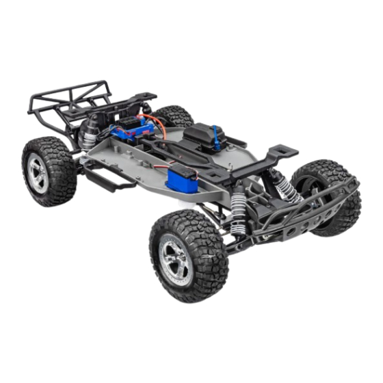
- Page 26 E. CHASSIS ASSEMBLY CHASSIS BAG E9. Install nerf bars onto the chassis Nerf Bar (2) 3x8mm BCS (4) 3x8mm Nerf Bar 3x8mm 3x8mm 3x8mm Nerf Bar Completed chassis assembly Check your assembly carefully. 26 • SLASH KIT...
-
Page 27: Suspension Installation
F. SUSPENSION INSTALLATION CHASSIS BAG F1. Attach the rear module to the chassis Rear 3x12mm BCS (4) Route ESC wires through the shock tower 3x12mm Module and connect to the motor. 3x12mm CHASSIS BAG F2. Attach the front module to the chassis 4x12mm BCS Front Bumper Mount 3x15mm... - Page 28 F. SUSPENSION INSTALLATION CHASSIS BAG F3. Center the steering servo F4. Install the servo horn onto the servo 3x14mm BCS (2) 3x14mm Turn transmitter on Plug charged battery into ESC (see Quick Start) (see Quick Start) Turn on the model Set Steering Trim to Zero (see Quick Start) (see Quick Start)
-
Page 29: Final Assembly
G. FINAL ASSEMBLY WHEELS AND TIRE BAG G1. Install tires on front and rear axles M4x0.7 NL (4) Assembled Front Tires and Wheels (2) Assembled Rear Tires and Wheels (2) Note the location marked on the inside of the wheel when installing. M4x0.7 NL Kit assembly complete SLASH KIT •... - Page 30 The best way to paint are extremely harmful. Spray the paint outdoors in the body is by using spray can paints. Genuine Traxxas well-ventilated areas only. Apply the paint to the body ProGraphix® paint is specially formulated for painting sparingly and in light coats.
- Page 31 APPENDIX BODY MOUNTING BAG Appendix 1: Body installation 3x10mm 3x10mm BCS (10) 3x10mm 3x10mm 3x8mm BCS (2) 3x10mm Clipless Latch Clipless Latch 3x8mm 3x10mm 3x6mm CCS (4) 3x6mm 3x8mm 3x10mm 3x6mm Front Latch Mounts (2) 3x6mm Front Latch Mount Rear Latch Mounts (2) Rear Latch Mount Front Latch Retainers (2) Front Latch Retainers (2)
- Page 32 LiPo and NiMH batteries. One NiMH Activate Low-Voltage Detection when or 2s LiPo battery equipped with a Traxxas iD® High Current connector using LiPo batteries. Refer to the EZ-Set is required. Traxxas Power Cell iD batteries are strongly recommended Tips card attached to your model, or see for maximum performance and safer charging.
- Page 33 Running in Wet Conditions while “steering” with the trim knob until the vehicle travels in Your Traxxas model is designed with water-resistant features to protect a straight line with no steering input. the electronics in the model (receiver, servos, electronic speed control).
- Page 34 NOTES 34 • SLASH KIT...
- Page 35 NOTES SLASH KIT • 35...
-
Page 36: Assembly Manual
6250 TRAXXAS WAY, McKINNEY, TEXAS 75070 1-888-TRAXXAS Entire contents ©2024 Traxxas. No part of this manual may be reproduced or distributed in print or electronic media 240426 KC24023-R00 without the express written permission of Traxxas. Specifications are subject to change without notice.
Need help?
Do you have a question about the SLASH BRUSHLESS and is the answer not in the manual?
Questions and answers