Table of Contents
Advertisement
Quick Links
Advertisement
Table of Contents

Related Manuals for Kohler 72-1500-00


Summary of Contents for Kohler 72-1500-00
- Page 1 72150000 Operation Manual Version 1.0.0.9 Automatic Transfer Switch Operation...
-
Page 2: Table Of Contents
Table of Contents Overview ……………………………………………………………….… Features …………………………………………………………………. Device Setup ……………………………………………………………. Setup by Part Number ………………………………………….. Setup by Voltage and Transition..……………………………..Manual Setup …………………………………………………..Set Menu Navigation ………………………………………….……..Display Settings ………..…………………………………………..Exercise Settings ………………………………………….………...…. Load Control ……………………………………………………….….… 11 Transitions ………………………………………………………….…..12 Standard …………………………..…………………………... -
Page 3: Overview
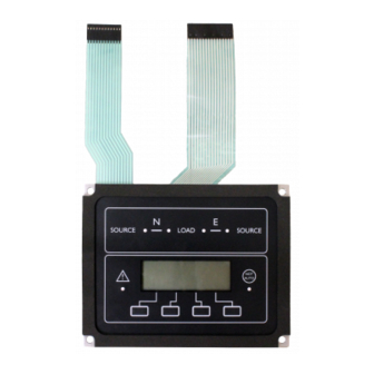
Overview ___________________________________________________________________________ The 721500 is a dropin replacement for the Kohler MPAC 1500/1200. The firmware has been designed to make a transition from the OEM controller to the Flight Systems replacement as transparent as possible. The human machine interface (HMI) is programmed so that settings and display functions are similar, if not identical, to the MPAC HMI. -
Page 4: Device Setup
From the main menu, press SET, enter the default password 0000 and select NEXT. Use the navigation keys to select Set Part Number and press NEXT. Set the part number of the OEM transfer switch. The Kohler part number will define the following settings. -
Page 5: Setup By Voltage And Transition
2. Setup Assist Similar to Setup by Part Number this will apply a set of safe default settings based on the users knowledge of the installation. You will be required to enter the correct settings for basic information about the transfer switch. A list of required information is provided below. -
Page 6: Set Menu Navigation
Set Menu Navigation ___________________________________________________________________________ Set Time/Date Time Date Set Exerciser (up to 16 events) Event – Enable/Disable Mode – Loaded/Unloaded Interval – Daily/Weekly/Monthly Repeat Rate – 112 Duration – Time Start Date – Date Prime Power Run – Not Supported v1.0.0. S1 Time Delays Engine Start Engine Cool down... - Page 7 Set Sources Preferred Source – Normal/Emergency *Phase Rotation – Disable, ABC, BAC *Inphase Monitor – Enabled/Disabled *Inphase Angle – Degrees *Fail to Sync – Enable/Disable – Delay *Voltage Differential – Percent Normal and Emergency Phases – Single / 3 phase Nominal Voltage Nominal Frequency Under Voltage Pickup ...
- Page 8 Inputs / Outputs Set Main Board I/O Set Inputs Input #12 Function – See I/O page 14 Set Output Output #12 Function – See I/O page 14 Set Auxiliary Board I/O Set Inputs Input #18 Function – See I/O page 14 Set Outputs Output#124 Function –...
-
Page 9: Display Settings
Display Settings ___________________________________________________________________________ Main Menu Use the left 2 buttons to navigate through the main menu. The main display will cycle through 8 screens to display various parameters and alternate functions. 1. Current Status, active time delay, and faults. Next Exercise (if enabled). Normal LL voltage and Emergency LL voltage. -
Page 10: Exercise Settings
Exercise Settings ___________________________________________________________________________ The 72150000 supports up to 16 exercise cycles. Each exercise cycle is entered as an event. When the control board is initially powered on it first searches all saved events to determine if they have already passed. All expired events are automatically updated to their next valid cycle and saved in eeprom. -
Page 11: Load Control
Load Control ___________________________________________________________________________ The 72150000 control supports up to 9 different load control outputs. The main board only supports 2 programmable outputs so the optional auxiliary board is required for setting up more than 2 load control outputs. Each load control output has a programmable disconnect and reconnect time for both source 1 and source 2 independently. -
Page 12: Transitions
Transitions ___________________________________________________________________________ Sequence of Operation Standard Transition 1. Preferred source fails. 2. Engine start delay expires and remote start contacts close. 3. Standby power is available. 4. Preferred to standby time delay expires. 5. Contactor transfers to standby power. 6. Load control reconnect timers expire and load control contacts close. 7. -
Page 13: Closed
Sequence of Operation Closed Transition 1. Preferred source fails. 2. Engine start delay expires and remote start contacts close. 3. Standby power is available. 4. Preferred to off time delay expires. 5. Contactor transfers to off position. 6. Off to standby time delay expires. 7. -
Page 14: I/O Options
I/O Options Programmable Inputs and Outputs ___________________________________________________________________________ Main Board I/O There are 2 inputs and 2 outputs available on the controller. Additional I/O can be added through the auxiliary I/O module. Output Functions cont. Input Functions Bypass Contactor Disabled Load Bank Active * Load Control Active Forced to OFF Inhibit Transfer... - Page 15 This page intentionally left blank.
-
Page 16: Alarms
Alarms ___________________________________________________________________________ The common fault is available as a programmable output. A latching fault must be cleared from the main display by pressing reset. Alarm groups are not supported in v1.0.0.9. Alarm Group 1 – Currently in development Alarm Group 2 – Currently in development Auxiliary I/O Module ___________________________________________________________________________... -
Page 17: Calibration
Calibration ___________________________________________________________________________ Should the controller require calibration, the calibration function can be accessed from the main menu > SET > CALIBRATION. Proper calibration will require taking a physical measurement from both line to line and line to neutral depending on the voltage configuration. Calibration Normal LL L1 –... -
Page 18: Factory Default Settings
Factory Default Settings ___________________________________________________________________________ Factory defaults can be set by navigating to the Set Factory Defaults entry in the SET menu. Applying factory defaults will overwrite all previous parameters and clear all exercise cycles, load control configurations for source 1 and source 2, all I/O settings, and calibration settings returned to default. -
Page 19: Modbus Communications
Modbus Communications _______________________________________________________________________________ This page intentionally left blank. - Page 20 Modbus Communications __________________________________________________________________________ Supported registers v1.0.0.4...
-
Page 21: Firmware Revisions
Firmware Revisions _______________________________________________________________________________ Version 1.0.0.1 Calibration Settings New factory default settings for calibration. Bugfix Correction to calibration settings. Emergency source using calibration points from Normal for L1L0 and L2L0. Version 1.0.0.2 (New Features) Contrast Adjustment Indicators set on to indicate when contrast adjustment is active. Contrast Adjustment ...
Need help?
Do you have a question about the 72-1500-00 and is the answer not in the manual?
Questions and answers