
Related Manuals for Kohler Decision-Maker MPAC 750


Summary of Contents for Kohler Decision-Maker MPAC 750
- Page 1 Operation Automatic Transfer Switches Controls: Decision-Makerr MPAC 750 Transfer Switch Model: TP-6865 4/14a...
-
Page 3: Table Of Contents
Table of Contents Safety Precautions and Instructions ............Introduction . - Page 4 Table of Contents, continued Communications Setup ..........4.3.1 Modbus Serial Communication Setup .
-
Page 5: Safety Precautions And Instructions
Safety Precautions and Instructions Accidental Starting Hazardous Voltage/ IMPORTANT SAFETY INSTRUCTIONS. Electromechanical equipment, Moving Parts including generator sets, transfer WARNING switches, switchgear, and accessories, can cause bodily harm and pose DANGER life-threatening danger when improperly installed, operated, maintained. To prevent accidents be aware of potential dangers and act safely. - Page 6 Heavy Equipment Making line auxiliary WARNING connections. Hazardous voltage can cause severe injury or death. To WARNING prevent electrical shock deenergize the normal power source before making any line or auxiliary connections. Servicing transfer switch Hazardous voltage. controls and accessories within the Can cause severe injury or death.
-
Page 7: Introduction
Keep this manual with the equipment for future reference. Information in this publication represents data available at the time of print. Kohler Co. reserves the right to List of Related Materials change this literature and the products represented... -
Page 8: Service Assistance
Visit the Kohler Power Systems website at Phone: (86) 21 6288 0500 KOHLERPower.com. Fax: (86) 21 6288 0550 Look at the labels and stickers on your Kohler product India, Bangladesh, Sri Lanka or review the appropriate literature or documents India Regional Office included with the product. -
Page 9: Section 1 Operation
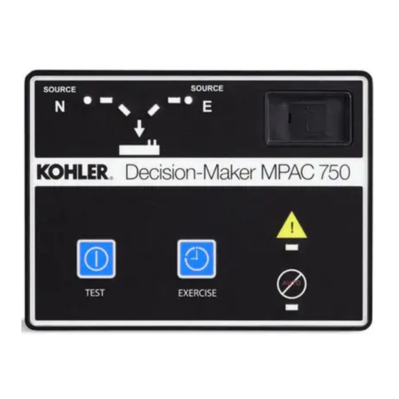
Section 1 Operation Introduction the transfer switch. In most applications, Source N is the utility source, and Source E is the standby generator set. This section contains operation instructions, including: The engine start contacts are associated with Source E. User interface panel, with pushbuttons and LED The Preferred Source is the source that will be used if indicators both sources are available. -
Page 10: Led Indicators
Test 1.3.2 LED Indicators LEDs on the user interface indicate contactor position, Use the Test button to: source availability, faults, and other conditions. The table in Figure 1-2 describes the functions of the LED Start and run the generator set (unloaded test). indicators. -
Page 11: Automatic Operation Test
Press and hold the Test pushbutton for about 2 seconds Automatic Operation Test Procedure to end the test. The retransfer sequence operates as 1. Check the controller LED indicators to verify that though Source N has been restored after a failure. The the Source N Position and Source N Available load is transferred back to source N. -
Page 12: Exercise
Exercise unloaded exercise. During an unloaded exercise, the Source E available LED flashes, 0.5 seconds on and 2 Set the exerciser after the ATS is installed. The exercise seconds off. automatically runs the generator set for 20 minutes each week. 1.6.3 Loaded Exercise If a system test is active when the exercise is scheduled... -
Page 13: Warnings And Faults
Warnings and Faults ATS warnings and faults are shown in Figure 1-5. There are three types of warning/fault conditions: When a fault exists, the System Alert indicator LED turns Warning. Warnings automatically reset with a source on and the related output is activated. If the output is availability change or a transfer request. -
Page 14: Fault Reset
Reset to Default Settings A personal computer with Kohlerr SiteTecht software can be used to reset the controller to factory defaults, if necessary. SiteTech software is only available to Kohler authorized distributors or dealers. Note: Resetting to the default parameters will reset all parameters, including the system voltage and frequency, to a factory default setting. -
Page 15: Section 2 Sequence Of Operation
Section 2 Sequence of Operation Controller Power- -up/Reset Sequence of Operation Following is an explanation of the sequence of operation The Sequence of Operation describes the transfer when power is initially applied to the controller or a switch normal operation. The MPAC 750 controller controller reset occurs. -
Page 16: Test Sequence
2.2.3 Test Sequence Unloaded Exercise Sequence Ends 1. Engine cooldown time delay expires. Unloaded Test Function is Initiated 2. The engine start contacts open, signaling the 1. The generator set is signaled to start. generator to stop. 2. The generator starts and Source E becomes Loaded Exercise Sequence Starts available. -
Page 17: Section 3 Settings
Modbus. SiteTech software is available transfer-to-standby time delay, the transfer sequence is to Kohler authorized distributors and dealers. cancelled and the load is not transferred to the standby Note: Use caution when changing transfer switch source. -
Page 18: Voltage Pickup And Dropout Settings
15_ to 5_ before synchronism only. Settings can be changed using a personal computer The factory settings and adjustment ranges for the time and Kohler SiteTech software or over Modbus. Contact delays are shown in Figure 3-3. your distributor or dealer for service. -
Page 19: Input Functions
3.6.1 Input Functions 3.6.2 Output Functions Available input functions are shown in Figure 3-4. Some Output functions are shown in Figure 3-5. Information inputs will trigger an indicator LED on the user interface about selected output functions is shown below. Refer and/or display a message on the LCD screen when they to the section number shown in Figure 3-5 for more are activated. -
Page 20: Common Alarms
Common Alarms Communications Functions can be assigned to two alarm groups. The Use a personal computer with Kohler SiteTech software or Modbus to set the communication parameters for groups can then be assigned to programmable outputs, serial or Ethernet connections. -
Page 21: Section 4 Communications
USB Port SiteTech Connection with a USB port and a Modbus port with an RS-485 connector. An optional Ethernet accessory board is A personal computer and Kohler SiteTech software can available. be used for changing controller settings. Use a USB cable to connect the controller to a personal computer. -
Page 22: Modbus Connection
4.2.2 Modbus Connection See Figure 4-2 and Figure 4-3 for the RS-485 Modbus connector location. The Modbus port on the controller circuit board is Port 0. Use serial connections to TB2 on the controller board to connect the transfer switch to a personal computer for system monitoring, the optional remote annunciator, or a Modbus network. - Page 23 RS-485 * USB port Input Cable shield USB to RS-485 port Device converter ] Terminating resistor may be required [ (121 Ohms) USB port RS-485 * USB to RS-485 Device port converter ] Device Cable shield Last Output Device Terminating resistor [, (121 Ohms) Customer connections * Use Belden #9841 or equivalent shielded, twisted-pair...
-
Page 24: Ethernet Connection (Optional)
MPAC 750 controller. The communication board Use the Setup menus or a personal computer connects to the controller board as shown in Figure 4-6. connected to the controller’s USB port and Kohler SiteTech software communication parameters. The Ethernet communication board may have a default IP address assigned at the factory for test purposes. - Page 25 MPAC Controller with Ethernet comm. Modbusr TCP/IP board Category 5e Ethernet IP xx.xx.xx.03 Modbusr Network TCP/IP Modbusr TCP/IP Modbusr Category 5e IP xx.xx.xx.02 RS-485 Device Device Converter, Modbusr Modbusr/Ethernet TCP/IP RS-485 RS-485 IP xx.xx.xx.05 Device Device RS-485 IP xx.xx.xx.01 Last device Terminating resistor (121 Ohms) Figure 4-8...
-
Page 26: Communications Setup
See Figure 4-9 for a summary of the following settings. connect the MPAC controller to a personal computer. Then use Kohler SiteTech software to set the DHCP Enabled. Factory set to False. Setting this communication parameters for serial or Ethernet parameter to True enables dynamic host configuration connections. - Page 27 Setting Range Default Notes Modbus Enabled True or False True Enable for network communication through the ethernet port. Modbus Baud Rate 9600, 19200, 57600 19200 Baud rate in bits per second for serial communication between the controller and a personal computer’s COM port. Modbus Slave Address 001-247 Address for the RS-485 serial port (on the controller board).
- Page 28 * Obtain from the local network administrator Figure 4-10 Communications Parameters in Kohler SiteTech Software Section 4 Communications TP-6865 4/14...
-
Page 29: Parameter Files
Parameter Files Controller Firmware Updates The parameter setting files can be exported to a Kohler may release updated versions of the controller personal computer (PC) using Kohlerr SiteTecht firmware. A personal (laptop) computer connected to software. Use a USB cable to connect the PC to the the USB port and Kohlerr SiteTecht software are controller. - Page 30 Notes Section 4 Communications TP-6865 4/14...
-
Page 31: Section 5 Scheduled Maintenance
Section 5 Scheduled Maintenance Introduction Disabling the generator set. Accidental starting can cause severe injury or death. Before working on the generator set or equipment connected to the set, disable the Regular preventive maintenance ensures safe and generator set as follows: (1) Press the generator set off/reset reliable operation and extends the life of the transfer button to shut down the generator set. -
Page 32: Testing
Testing Grounding electrical equipment. Hazardous voltage can cause severe injury or death. Electrocution is possible whenever electricity is present. Ensure you comply with all 5.2.1 Weekly Generator Set Exercise applicable codes and standards. Electrically ground the generator set, transfer switch, and related equipment and Use the exerciser to start and run the generator set electrical circuits. -
Page 33: Inspection And Service
Inspection and Service Signs of corrosion Worn, missing, or broken components Contact an authorized distributor/dealer to inspect and service the transfer switch annually and also when any Loose hardware wear, damage, deterioration, or malfunction of the transfer switch or its components is evident or Wire or cable insulation deterioration, cuts, or suspected. -
Page 34: Service Schedule
Service Schedule performed by an authorized distributor/dealer except for activities designated by an X, which may be performed by the switch operator. Follow service schedule below recommended service intervals. Have all service Adjust, Visually Repair, Section Inspect Replace System Component or Procedure Check Clean Test... -
Page 35: Section 6 Accessories
Section 6 Accessories Introduction The controller disconnect switch allows disconnection of the power to the controller during maintenance and This section describes the hardware options that are service. See Figure 6-1. available transfer switches equipped with Note: Disable the generator set before using the Decision-Makerr MPAC 750 controls. -
Page 36: Ethernet Board
Change the IP address to an address owned by the user. Use Programmable exerciser features include: Kohler SiteTech software to assign a new IP address Seven-day programmable timer allows scheduling and port number. -
Page 37: Heater
Heater An anti-condensation heater kit is available. The strip heater is controlled by a hygrostat to raise the temperature inside the enclosure above the dew point to prevent condensation. Figure 6-4 shows typical locations of the heater kit components inside the enclosure. -
Page 38: Surge Protection (Spd)
Surge Protection (SPD) A surge protection device (SPD) is available for the transfer switch. Installed on the Normal source side, the SPD protects the system from voltage surges, preventing damage to household loads. The SPD resets automatically. See Figure 6-7 for the typical SPD assembly location inside the ATS enclosure. - Page 39 Figure 6-9 SPD Wiring Diagram, GM89992 TP-6865 4/14 Section 6 Accessories...
-
Page 40: Spd Status Indicators
6.6.1 SPD Status Indicators SPD Remote Status Indication Specification Contact rating 1 A @ 250 VAC A status indicator on each Surge Protection Device (SPD) module indicates the SPD condition. Wire Size 16 AWG Figure 6-10. A green indicator shows that the SPD is Figure 6-11 Remote Status Indicator Contact providing protection. -
Page 41: User Interface Cover
User Interface Cover SPD Replacement Procedure Note: The cartridges are keyed for the phases or the The gasket-sealed, hinged user interface cover neutral. Be sure to obtain the correct service part prevents unauthorized access to the transfer switch for each cartridge. See the transfer switch parts controls and protects the user interface from harsh catalog for service part numbers. - Page 42 Notes Section 6 Accessories TP-6865 4/14...
-
Page 43: Appendix A Abbreviations
(2 bytes) est. estimated Canadian Electrical Code KBus Kohler communication protocol E-Stop emergency stop cert. certificate, certification, certified kilogram etc. et cetera (and so forth) cubic feet per hour TP-6865 4/14 Appendix 43... - Page 44 kg/cm kilograms per square National Bureau of Standards remote terminal unit centimeter normally closed room temperature vulcanization kilogram-meter National Electrical Code read/write kg/m kilograms per cubic meter NEMA National Electrical Society of Automotive kilohertz Manufacturers Association Engineers kilojoule NFPA National Fire Protection scfm standard cubic feet per minute Association...
- Page 45 Notes TPMPFP-6865 4/14...
- Page 46 Notes TPMPFP-6865 4/14...
- Page 48 For the nearest sales/service outlet in the US and Canada, phone 1-800-544-2444 KOHLERPower.com Kohler Power Systems Asia Pacific Headquarters TP-6865 4/14a 7 Jurong Pier Road Singapore 619159 Phone (65) 6264-6422, Fax (65) 6264-6455 E 2014 by Kohler Co. All rights reserved.
Need help?
Do you have a question about the Decision-Maker MPAC 750 and is the answer not in the manual?
Questions and answers
MPAC ATS 4 clicks but no transfer. Is there a troubleshooting procedure