Table of Contents
Advertisement
Quick Links
Introduction
The IQ201 panel mount universal process indicator is a precision digital indicator for interfacing to and measuring most
process variables. The IQ201 is capable of measuring and processing variables such as mA, Volts, Potentiometers,
Frequency, Counting, Ohms, mV, Thermocouples, RTDs and also has built in functions such as an Event Timer, Real
Time Clock (RTC option required) and a manual analog output station (Analog out option required). The IQ201 also
includes a multiple output excitation voltage selection for sensor excitation of 2 or 3 wire transmitters, encoders,
potentiometers and many more.
Calibration of the analog process variables is simply done by either entering in the display range selection or by direct
sensor injection calibration.
The high bright 6-digit 14 segment LED displays make for easy setup and readability. A simple menu system with built in
help hints allows for easy configuration of display and sensor settings.
A universal mains switch mode power supply (85-264VAC) is provided as standard but an optional low voltage (10-
30VDC) isolated power supply or a high voltage (25-70VDC) isolated power supply can be installed.
RS232 communications is supplied as standard with the MODBUS™ RTU and MODBUS™ ASCII protocol. A simple
ASCII out protocol is also provided for serial printing and communicating to large displays. A second communication
RS485 interface can be added in conjunction with the standard RS232 interface.
The IQ201 also has an analog out or an isolated analog out option to generate a precision 0/4-20mA and 0-10V analog
output signal.
The IQ201 also includes advanced features such as user input linearisation, max/min recording, programmable front
push buttons, programmable digital inputs, security menu lockout, advanced digital filtering, plus many more to provide a
truly universal process indicator.
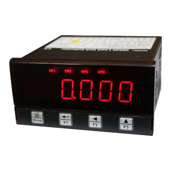
IQ201
Panel Mount Universal Process Indicator
Operating Manual – English 1.02
mA
Volts
mV
Frequency
Counting
Thermocouples
Ohms
RTD
Potentiometer
Event Timer
Real Time Clock
Manual Analog Out Station
Advertisement
Table of Contents

Subscribe to Our Youtube Channel
Related Manuals for INSTROTECH IQ201

Summary of Contents for INSTROTECH IQ201
- Page 1 ASCII out protocol is also provided for serial printing and communicating to large displays. A second communication RS485 interface can be added in conjunction with the standard RS232 interface. The IQ201 also has an analog out or an isolated analog out option to generate a precision 0/4-20mA and 0-10V analog output signal.
- Page 2 IQ201 Panel Mount Universal Process Indicator Page 2 1 Features High bright 6-digit 14 segment LED displays for easy setup and calibration Inputs for mA, Volts, Potentiometer, Frequency, Counting, mV, Thermocouples, Ohms & RTDs. Built in functions such as an Event Timer, Real Time Clock (RTC option required), manual setpoint station (Analog output option required) ...
- Page 3 IQ201 Panel Mount Universal Process Indicator Page 3 This instrument is marked with the international hazard symbol. It is important to read this manual before installing or commissioning your panel meter as it contains important information relating to safety and Electromagnetic Compatibility EMC.
-
Page 4: Specifications
IQ201 Panel Mount Universal Process Indicator Page 4 2 Specifications General: Display 6-Digit, 13.8mm (0.543”) 14 segment high brightness red LED Display range -199999 to +999999 Status LEDS 5 LEDs (SP1 to SP4 & Totaliser) Digital Inputs 2 Programmable digital inputs Built in hysteresis, filter and input over voltage protection Maximum input voltage <30VDC... - Page 5 IQ201 Panel Mount Universal Process Indicator Page 5 Filter Moving average digital filter with programmable input step detection Conversion rate 10 updates/second Increment size 1, 2, 5, 10, 20, 50, 100, 200 Lineariser 16 Point Voltage Input: Measurement ranges +-23V (Bi-polar)
- Page 6 IQ201 Panel Mount Universal Process Indicator Page 6 Minimum resistance of Potentiometer 1K Ohm Accuracy 0.05% of reading +-20uV (Typically 0.02%) Temperature Coefficient ° <= +-2uV/ Input impedance >1Mohm Decimal Point Programmable on all digits Filter Moving average digital filter with programmable input step detection...
- Page 7 IQ201 Panel Mount Universal Process Indicator Page 7 RTD sensors 2 and 3 wire supported. (Pin 3 and 4 on the input connector must be linked for 2 wire RTDs) Display Resolution ° ° 0.1 or 1 Unit ° °...
- Page 8 IQ201 Panel Mount Universal Process Indicator Page 8 RS232 Communications (Standard) Baud rate: 1200,2400,4800,9600,19200,38400,57600,115200 Data bits: 7 or 8 bits Parity: Odd, Even or None Stop bits: 1 or 2 stop bits Non isolated RS485 Communications (Optional) Baud rate: 1200,2400,4800,9600,19200,38400,57600,115200...
-
Page 9: Installation
IQ201 Panel Mount Universal Process Indicator Page 9 3 Installation 3.1 Dimensions & Front panel layout Alarm Status Indication 6-Digit 14 segment high brightness LED display Normal Display Mode: F1 Function key Normal Display Mode: Programming Mode: Print key / Press for 3 seconds Enter key. -
Page 10: Panel Cutout
Page 10 3.2 Panel Cutout A rectangular cutout measuring 92x45mm (3.62”x1.77”) must be made in the mounting enclosure. The IQ201 instrument should preferably be mounted in a grounded metal enclosure. The supplied o-ring must be attached to the front cover to provide sealing between the indicator and the mounting enclosure. - Page 11 IQ201 Panel Mount Universal Process Indicator Page 11 3.3 Hardware Connection (Lower Terminals)
- Page 12 IQ201 Panel Mount Universal Process Indicator Page 12 3.4 Hardware Connection (Upper Terminals – Option PCB)
-
Page 13: Opening The Unit
IQ201 Panel Mount Universal Process Indicator Page 13 3.5 Opening the Unit Make sure power and all connectors have been removed before opening the unit. To open the unit simply remove all the connectors from the rear and unscrew the 2 or 4 (Depending if an option board has been installed) screws and simply slide out the instrument from the enclosure. -
Page 14: Power Supply Wiring
3.8 Fuse Replacement The IQ201 contains a built in fuse. The fuse is a slow blow 2A Wickmann part number 3721200000. The fuse can also be purchased from RS Components part number 226-6599. The diagram below illustrates the position of the fuse on the... -
Page 15: Input Signal Connection
3.91 Current Input The IQ201 can accept a bi-polar mA signal between -20mA to +20mA. The IQ201 can also be used with 2 or 3 wire transmitters. An internal 24V excitation voltage can be used to power up an external sensor (Excitation voltage is jumper selectable, default setting is +24V). -
Page 16: Voltage Input
3.92 Voltage Input The IQ201 can accept a bi-polar voltage signal between -20V to +20V. An internal excitation voltage can be used to power up an external sensor (Excitation voltage is jumper selectable, default setting is +24V). Software ranges of the voltage signal are 0-2V, 0-5V, 1-5V, 0-10V, 2-10V, 0-15V, 3-15V, 0-20V or a user defined range. -
Page 17: Thermocouple Input
3.95 Ohms Input The IQ201 can measure resistance between 0 and 400 Ohms using either 2 wire or 3 wire ohms measurement. If using 2 wire ohms measurement then pin 3 & 4 on the input connector must be linked as in the diagram below. An internal excitation voltage can be used to power up an external sensor (Excitation voltage is jumper selectable, default setting is +24V). -
Page 18: Rtd Input
3.96 RTD Input The IQ201 can interface to a wide range of RTDs (See specification for a list of supported RTDs). The IQ201 can measure temperature using either 2 wire or 3 wire RTDs. The temperature can be displayed in degrees Celcius, Fahrenheit or absolute (Kelvin). -
Page 19: Potentiometer Input
Page 19 3.98 Potentiometer Input The IQ201 can read a potentiometer with a minimum resistance of 1K ohm. The potentiometer software has a programmable zero, span, decimal point, filter, calibration mode and 16 point lineariser. The internal excitation voltage jumper must be set to VREF. The VREF excitation voltage is a precision 2.048V with a maximum current of 2mA. -
Page 20: Digital Input Connection
3.10 Digital Input connection The IQ201 comes with 2 programmable digital inputs. The digital inputs can be used with either potential free contacts such as relay contacts, switches, transistor outputs or can be voltage driven. The inputs are not isolated from the instruments input circuitry. - Page 21 The RS485 protocol allows for a wired connection to be established as far as 4000ft (1200m). RS232 only allows for a wired connection up to 100ft (30.5m). The IQ201 includes an on-board termination resistor which can be selected by linking J1 on the option circuit board inside the IQ201. The termination resistor is 120 Ohms.
- Page 22 IQ201 Panel Mount Universal Process Indicator Page 22 3.13 Mechanical Relays (Optional) Up to 4 mechanical relays can be added as an option. Interposing relays are recommended for heavy duty applications. A R-C Snubber network or MOV maybe required for switching AC loads and a freewheeling diode or MOV maybe required for switching DC loads.
- Page 23 3.15 Analog Out / Isolated Analog Out (Optional) Analog out or an Isolated analog out option can be fitted to the IQ201. The Analog out uses a high precision 16 bit DAC (Digital to Analog converter) to provide analog ranges of 0-20mA, 4-20mA and 0-10V. The current output is source, not sink and can drive a maximum of 500Ω.
-
Page 24: Engineering Units
3.16 RTC Battery Replacement (Optional) The internal battery will have to be replaced if the IQ201 looses its time when the instrument is switched off and on. The battery is of type CR2032. The battery is located on the underside of the option circuit board. The diagram below shows the location of the battery. -
Page 25: Menu System
4.2 Built in Help Feature The IQ201 includes a menu help feature which gives a better explanation of the menu option. If navigating the menu system and no keys are pressed within 10 seconds, then a help hint will be scrolled across the screen. - Page 26 IQ201 Panel Mount Universal Process Indicator Page 26 Press the “Enter” key to see the setpoint 1 value. Press the “Up” key to increment the digit. Press the “Left” key to edited the next digit. Continue until the value has been set to the desired value.
- Page 27 IQ201 Panel Mount Universal Process Indicator Page 27 4.4 Main Menu The main menu is entered by pressing and holding down the menu key for 3 seconds. The following will be displayed. Use the Up, Left, Enter and Menu keys to navigate the menu system.
-
Page 28: Setpoint Values
IQ201 Panel Mount Universal Process Indicator Page 28 RS485 communications setup menu (Only shown if the RS485 option has been ordered) Function key setup menu Digital input setup menu Miscellaneous items setup menu Exit menu. Settings are saved on menu exit and the instrument will return to the normal display mode Back to the start of the main menu. -
Page 29: Input Configuration Menu
IQ201 Panel Mount Universal Process Indicator Page 29 4.6 Input Configuration Menu This menu selects and configures the input signal. Current Input Voltage input mV Input Frequency input Counter input Thermocouple input RTD Input Ohms Input Potentiometer input Event Timer Real Time clock (RTC option required) Manual analog output station. - Page 30 Select the display decimal point. Use the up arrow to select the decimal point. The IQ201 can be configured by using data either from the mA sensor datasheet (“0-20mA” or “4-20mA” selected) or by using direct mA signal injection (“mA CAL” selected).
- Page 31 IQ201 Panel Mount Universal Process Indicator Page 31 The following 3 menu items are only shown if “mA CAL” has been selected for the “RANGE” setting. Enter the value in mA that corresponds to the low display value (“DISP L”).
- Page 32 IQ201 Panel Mount Universal Process Indicator Page 32 The IQ201 instrument contains an advanced digital filter algorithm. The filter works by filtering small changes between measurements but will react instantaneously to a large step response. There are 2 settings that are used to setup the digital filter, namely the filter band and the filter time.
- Page 33 IQ201 Panel Mount Universal Process Indicator Page 33 Lineariser Sub-Menu For non-linear processes, up to 16 scaling points may be used to provide a piece-wise linear approximation. The greater the number of points the greater the accuracy. Each point has a real value and a corresponding display value. The real value is the actual value of the input as it would be with the lineariser feature turned off, the display value is the desired value.
- Page 34 For best results the system should be given a warm up time of a minimum of 15 minutes before calibration takes place and the 2 known signals should be as different from each other as possible to allow the IQ201 to try and obtain the greatest resolution.
- Page 35 Select the display decimal point. Use the up arrow to select the decimal point. The IQ201 can be configured by using data either from the Volts sensor datasheet or by using direct Volts signal injection (“V CAL” selected). Enter the display value of the system that corresponds to the low value of the “RANGE”...
- Page 36 IQ201 Panel Mount Universal Process Indicator Page 36 Enter the display value of the system that corresponds to the high value of the “RANGE” selection. E.G. if 2-10V is selected for “RANGE” then enter a value that corresponds to 10V. If “V CAL” has been selected for “RANGE” then enter the display value of the system that corresponds to the “HIGH V”...
- Page 37 IQ201 Panel Mount Universal Process Indicator Page 37 The IQ201 instrument contains an advanced digital filter algorithm. The filter works by filtering small changes between measurements but will react instantaneously to a large step response. There are 2 settings that are used to setup the digital filter, namely the filter band and the filter time.
- Page 38 IQ201 Panel Mount Universal Process Indicator Page 38 Lineariser Sub-Menu For non-linear processes, up to 16 scaling points may be used to provide a piece-wise linear approximation. The greater the number of points the greater the accuracy. Each point has a real value and a corresponding display value. The real value is the actual value of the input as it would be with the lineariser feature turned off, the display value is the desired value.
- Page 39 For best results the system should be given a warm up time of a minimum of 15 minutes before calibration takes place and the 2 known signals should be as different from each other as possible to allow the IQ201 to try and obtain the greatest resolution.
- Page 40 Select the display decimal point. Use the up arrow to select the decimal point. The IQ201 can be configured by using data either from the mV sensor datasheet or by using direct mV signal injection (“mV CAL” selected). Enter the display value of the system that corresponds to the low value of the “RANGE”...
- Page 41 The IQ201 instrument contains an advanced digital filter algorithm. The filter works by filtering small changes between measurements but will react instantaneously to a large step response. There are 2 settings that are used to setup the digital filter, namely the filter band and the filter time.
- Page 42 IQ201 Panel Mount Universal Process Indicator Page 42 See the paragraph above for an explanation of the filter band. Use the front panel push buttons to enter the filter band. Select the filter time. See the paragraph above for an explanation of the filter time.
- Page 43 For best results the system should be given a warm up time of a minimum of 15 minutes before calibration takes place and the 2 known signals should be as different from each other as possible to allow the IQ201 to try and obtain the greatest resolution.
- Page 44 Apply the low calibration signal to the instrument and then press enter. The IQ201 will start to average and calculate the volts value that corresponds to the low calibration signal. Done! The low calibration signal can now be removed. The low display value and its corresponding volts value will be saved.
- Page 45 Use the up arrow to select the decimal point. The IQ201 caters for a wide range of applications. The display value can be adapted to these applications using the factor and scale variables. Display Value = Input x Factor x Scale.
- Page 46 IQ201 Panel Mount Universal Process Indicator Page 46 Select the filter gate time. The frequency will be measured over this interval. 0.5 Seconds gate time 1 Second gate time 5 Seconds gate time Back to the start of the Frequency setup menu.
- Page 47 Use the up arrow to select the decimal point. The IQ201 caters for a wide range of applications. The display value can be adapted to these applications using the factor and scale variables. Display Value = Input x Factor x Scale.
- Page 48 IQ201 Panel Mount Universal Process Indicator Page 48 Enter the reset / preset value of the Counter. Use the front panel push buttons to enter the reset preset value. Back to the start of the Counter setup menu.
- Page 49 IQ201 Panel Mount Universal Process Indicator Page 49 4.6.6 Thermocouple Input Configuration menu This menu option allows the user to set the thermocouple input settings. Select the Thermocouple type Select the method of the thermocouple cold junction compensation Internal temperature sensor (default) User manual input Cold junction compensation temperature value.
- Page 50 IQ201 Panel Mount Universal Process Indicator Page 50 4.6.7 RTD Input Configuration menu This menu option allows the user to set the RTD input settings. Select the RTD type Pt50 Pt100 Ni100 Ni120 Select the display decimal point. Only a decimal point of 1 decimal place or no decimal place can be selected.
- Page 51 Select the display decimal point. Use the up arrow to select the decimal point. The IQ201 can be configured by using data either from the Ohm sensor datasheet or by using direct ohm signal injection (“OHM.CAL” selected). Enter the display value of the system that corresponds to the low value of the “RANGE”...
- Page 52 The IQ201 instrument contains an advanced digital filter algorithm. The filter works by filtering small changes between measurements but will react instantaneously to a large step response. There are 2 settings that are used to setup the digital filter, namely the filter band and the filter time.
- Page 53 IQ201 Panel Mount Universal Process Indicator Page 53 See the paragraph above for an explanation of the filter band. Use the front panel push buttons to enter the filter band. Select the filter time. See the paragraph above for an explanation of the filter time.
- Page 54 For best results the system should be given a warm up time of a minimum of 15 minutes before calibration takes place and the 2 known signals should be as different from each other as possible to allow the IQ201 to try and obtain the greatest resolution.
- Page 55 Apply the low calibration signal to the instrument and then press enter. The IQ201 will start to average and calculate the volts value that corresponds to the low calibration signal. Done! The low calibration signal can now be removed. The low display value and its corresponding volts value will be saved.
- Page 56 Apply the low calibration signal to the instrument and then press enter. The IQ201 will start to average and calculate the value that corresponds to the low calibration signal. Done! The low calibration signal can now be removed. The low...
- Page 57 The IQ201 instrument contains an advanced digital filter algorithm. The filter works by filtering small changes between measurements but will react instantaneously to a large step response. There are 2 settings that are used to setup the digital filter, namely the filter band and the filter time.
- Page 58 IQ201 Panel Mount Universal Process Indicator Page 58 See the paragraph above for an explanation of the filter band. Use the front panel push buttons to enter the filter band. Select the filter time. See the paragraph above for an explanation of the filter time.
- Page 59 IQ201 Panel Mount Universal Process Indicator Page 59 Note: If the measured value is above the last actual point then the lineariser will use the last 2 points to calculate the slope and similarly is the measured value is below the first actual point then it will use the first 2 points to calculate the slope.
- Page 60 IQ201 Panel Mount Universal Process Indicator Page 60 4.6.10 Event Timer Configuration menu This menu option allows the user to set the Event Timer settings. Select the mode of the Event Timer. Event Timer counts down Event Timer counts up Select the Event Timer time format Seconds only (0.01 second resolution)
- Page 61 IQ201 Panel Mount Universal Process Indicator Page 61 4.6.11 Real Time Clock setup menu. (RTC option required) This menu option allows the user to set the RTC (Real Time Clock). This menu option is only displayed if the RTC option has been ordered.
-
Page 62: Alarm Configuration Menu
IQ201 Panel Mount Universal Process Indicator Page 62 4.7 Alarm Configuration Menu This menu configures the alarm parameters. This menu is only shown if any of the alarm options have been ordered. The below setup menu is identical for each of the alarms. - Page 63 IQ201 Panel Mount Universal Process Indicator Page 63 Enter the deviation high value. The high value of the band is the set point plus the deviation high value. This menu option is only shown if the alarm mode is set to deviation.
- Page 64 IQ201 Panel Mount Universal Process Indicator Page 64 The above diagram illustrates the use of a high alarm with hysteresis and on/off delay. 4.8 Analog Out Configuration Menu This menu configures the analog output parameters. This menu is only shown if the analog output option has been ordered.
- Page 65 IQ201 Panel Mount Universal Process Indicator Page 65 Select the analog out type. The Analog output is disabled. The analog output will be set to 0 to 20mA The analog output will be set to 4 to 20mA The analog output will be set to 0 to 10V Enter the analog output low value.
- Page 66 This menu configures the RS232 and RS485 serial port parameters. The RS232 communication port is standard on the IQ201 but the RS485 menu will only be shown if the RS485 option has been ordered. The IQ201 has 3 built in communication protocols: 1) MODBUS™...
- Page 67 IQ201 Panel Mount Universal Process Indicator Page 67 4800 Baud. 9600 Baud. 19200 Baud. 38.4k Baud. 57.6k Baud. 115.2k Baud. Select the communication data bits 7 data bits. 8 data bits. Select the communication parity. No parity. Even parity. Odd parity.
- Page 68 IQ201 Panel Mount Universal Process Indicator Page 68 Minimum value recorded Maximum value recorded This menu option is only shown if the ASCII Out mode is selected. Print on demand by either pressing the front push button or by a digital input.
-
Page 69: The Modbus Protocol
IQ201 Panel Mount Universal Process Indicator Page 69 4.9.2 The Modbus Protocol The IQ series instruments modbus implementation is based on the following documents: “MODBUS over Serial Line Specification and Implementation Guide V1.02” from Modbus-IDA.ORG. “MODBUS Application Protocol Specification V1.1b” from Modbus-IDA.ORG. - Page 70 IQ201 Panel Mount Universal Process Indicator Page 70 Address Data Type Operation Description 32 bit unsigned Serial Number High Word 32 bit unsigned Serial Number Low Word 8 bit unsigned Model Number 16 bit unsigned Firmware Version 32 bit signed...
- Page 71 IQ201 Panel Mount Universal Process Indicator Page 71 8 bit unsigned Alarm 2 Assignment 0: Input Selection 1: Min 2: Max 8 bit unsigned Alarm 2 Mode 0: Off 1: Low 2: High 8 bit unsigned Alarm 2 logic 0: Normal...
- Page 72 IQ201 Panel Mount Universal Process Indicator Page 72 0: Off 1: Low 2: High 8 bit unsigned Alarm 4 logic 0: Normal 1: Inverted 16 bit unsigned Alarm 4 Hysteresis 16 bit unsigned Alarm 4 Deviation low 16 bit unsigned...
- Page 73 IQ201 Panel Mount Universal Process Indicator Page 73 0: 1200 1: 2400 2: 4800 3: 9600 4: 19200 5: 38400 6: 57600 7: 115200 8 bit unsigned COM 1 (RS232) Data Bits 0: 7 Bits 1: 8 Bits 8 bit unsigned...
- Page 74 IQ201 Panel Mount Universal Process Indicator Page 74 8 bit unsigned F1 Key Assignment 0: None 1: Min/Max Toggle 2: Min/Max Value Reset 3: Latch Reset 4: Zero 5: Edit SP1 6: Edit SP2 7: Edit SP3 8: Edit SP4...
- Page 75 IQ201 Panel Mount Universal Process Indicator Page 75 1: Min/Max Toggle 2: Min/Max Value Reset 3: Latch Reset 4: Zero 5: Display Hold 6: Print 7: Counter Reset/Preset 8: Event timer start 9: Event timer stop 10: Event timer start/stop...
- Page 76 IQ201 Panel Mount Universal Process Indicator Page 76 32 bit signed Lineariser Display Point 5 Low Word 32 bit signed Lineariser Real Point 6 High Word 32 bit signed Lineariser Real Point 6 Low Word 32 bit signed Lineariser Display Point 6 High Word...
- Page 77 IQ201 Panel Mount Universal Process Indicator Page 77 32 bit signed Lineariser Real Point 16 High Word 32 bit signed Lineariser Real Point 16 Low Word 32 bit signed Lineariser Display Point 16 High Word 32 bit signed Lineariser Display Point 16 Low Word...
- Page 78 IQ201 Panel Mount Universal Process Indicator Page 78 8 bit unsigned Counter mode 8 bit unsigned Counter Decimal Point 32 bit signed Counter Factor High Word 32 bit signed Counter Factor Low Word 8 bit unsigned Counter Scale 32 bit signed...
- Page 79 IQ201 Panel Mount Universal Process Indicator Page 79 8 bit unsigned Potentiometer Filter Time 8 bit unsigned Potentiometer Filter Band 32 bit signed Potentiometer Low Display High Word 32 bit signed Potentiometer Low Display Low Word 32 bit signed Potentiometer High Display High Word...
- Page 80 IQ201 Panel Mount Universal Process Indicator Page 80 4.10 Function Key Configuration Menu This menu configures the front panel function key push buttons. Three of the front panel push buttons can be user configured for specific functions as listed below. Certain options will be only be shown depending on the input type selected.
- Page 81 IQ201 Panel Mount Universal Process Indicator Page 81 4.11 Digital Input Configuration Menu This menu configures the two digital inputs. The digital inputs can be configured for specific functions as listed below. Certain options will be only be shown depending on the input type selected.
-
Page 82: Miscellaneous Configuration Menu
IQ201 Panel Mount Universal Process Indicator Page 82 4.12 Miscellaneous Configuration Menu This menu configures the miscellaneous functions of the instrument. Select this option if you want to password protect the menu system. Select “NONE” for no menu protection, “FULL” for all menu options to be password protected, or “ALM.VAL”... -
Page 83: Error Messages
IQ201 Panel Mount Universal Process Indicator Page 83 This menu option allows access to technical functions such as input signal and analog output calibration. These functions are accessed by the factory during the calibration of the instrument. Please consult the factory for more information. -
Page 84: Other Error Messages
IQ201 Panel Mount Universal Process Indicator Page 84 Other Error Messages: Unit settings CRC error. Load default settings to restore to factory defaults. If the error message still persists then it could possibly be a non-volatile memory failure in which case the instrument will then have to be returned to the factory. -
Page 85: Firmware Upgrading
7 Firmware Upgrading The IQ201 process indicator can be upgraded in the field by connecting the RS232 port to a PC and running the firmware update program. Note that only the RS232 port can be used to upgrade the firmware. -
Page 86: Ordering Information
10 Ordering Information Add option codes to suffix of model number separated by hyphens. Example: (IQ201 Process indicator with 2 mechanical relays, analog output and an additional RS485 interface) IQ201-711-730-740 Option part numbers: 700 - Low voltage 10-30VDC isolated power supply... -
Page 87: Warranty
IQ201 Panel Mount Universal Process Indicator Page 87 11 Notice Specifications of the products displayed herein are subject to change without notice. Infiniteq cc, or anyone on its behalf, assumes no responsibility or liability for any errors or inaccuracies. Information contained herein is intended to provide a product description only. No license, express or implied, by estoppel or otherwise, to any intellectual property rights is granted by this document.
Need help?
Do you have a question about the IQ201 and is the answer not in the manual?
Questions and answers