Table of Contents
Advertisement
Available languages
Available languages
Quick Links
MANUALE DI ISTRUZIONE PER PANNELLO DI CONTROLLO
I
Art. 460.01 PER GENERATORI PLASMA HQC CON GAS
CONSOLE AUTOMATICA
CONTROL PANEL Art 460.01 FOR PLASMA HQC POWER
GB
SOURCE WITH AUTOMATIC GAS CONSOLE INSTRUCTION
MANUAL.
Parti di ricambio e schema elettrico.
Spare parts and wiring diagram.
3.300.045-A
pag. 2
page 14
page 26
02-02-2016
Advertisement
Chapters
Table of Contents

Related Manuals for Cebora 460.01

Summary of Contents for Cebora 460.01
- Page 1 MANUALE DI ISTRUZIONE PER PANNELLO DI CONTROLLO Art. 460.01 PER GENERATORI PLASMA HQC CON GAS pag. 2 CONSOLE AUTOMATICA CONTROL PANEL Art 460.01 FOR PLASMA HQC POWER SOURCE WITH AUTOMATIC GAS CONSOLE INSTRUCTION page 14 MANUAL. Parti di ricambio e schema elettrico.
-
Page 2: Precauzioni Di Sicurezza
IMPORTANTE: PRIMA DELLA MESSA IN - Non avvolgere i cavi di massa e della pinza OPERA DELL'APPARECCHIO LEGGERE IL porta elettrodo o della torcia attorno al corpo. CONTENUTO DI QUESTO MANUALE E - Non stare mai tra il cavo di massa e quello della CONSERVARLO, PER TUTTA LA VITA pinza portaelettrodo o della torcia. -
Page 3: Targa Delle Avvertenze
Targa delle AVVERTENZE. L’arco plasma può provocare lesioni ed ustioni. Il testo numerato seguente corrisponde alle caselle 2.1 Spegnere l’alimentazione elettrica prima di numerate della targa. smontare la torcia. 2.2 Non tenere il materiale in prossimità del percorso di taglio. 2.3 Indossare una protezione completa per il corpo. -
Page 4: Table Of Contents
SOMMARIO REPARAZIONE ED ESECUZIONE DELLA MARCATURA PRECAUZIONI DI SICUREZZA......2 ) ........... 10 ARCATURA AVVERTENZE......... 3 ARGA DELLE FUNZIONI DI SERVIZIO........11 INSTALLAZIONE..........5 ....11 OMPONENTI DEL SISTEMA E SUO STATO ..........5 ....12 ESSA IN OPERA REPARAZIONE ED ESECUZIONE DEL DESCRIZIONE SISTEMA. -
Page 5: Installazione
Manuali di Istruzioni al paragrafo “Installazione”. DESCRIZIONE SISTEMA. Il Pannello di Controllo HQC (Art. 460.01) permette la gestione della gas console automatica di un impianto Cebora della linea HQC, indipendentemente dal tipo di interfaccia (digitale o analogica) con il CNC/Robot. -
Page 6: Impiego
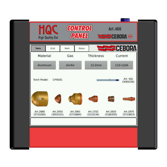
IMPIEGO Descrizione del pannello di controllo HQC Dal pannello di controllo HQC, si gestiscono diverse funzioni dell’impianto con gas console automatica. In particolare, si possono: selezionare ed impostare i parametri del tipo di lavoro da effettuare: taglio (CUT), bulinatura (SPOT MARKING), marcatura (MARK);... - Page 7 La seconda predisposizione da effettuare, in sequenza, è la selezione indicata in figura 2 (scheda Taglio). Il tipo di lavorazione corrente è impostato dal CNC “runtime”: se esso è in modalità taglio allora appaiono le parentesi quadre [Taglio]. Premesso che il sistema si predispone, in automatico, con i flussi e la corrente indicati nelle tabelle di taglio (vedi manuale 3.300.350), è...
- Page 8 Qualora il valore di pressione impostata sia esterno all’intervallo consigliato, si accendono, di colore arancione, i tasti – (pressione inferiore alla minima) ovvero + (pressione superiore alla massima). Inoltre, qualora manchi l’alimentazione dell’aria, il valore di pressione impostato è di colore rosso. Nel riquadro Corrente, posizionato in basso a sinistra, è...
- Page 9 4.2.1 Preparazione ed esecuzione della bulinatura (Spot Marking) La bulinatura o marcatura spot è un particolare tipo di marcatura ove la traccia consiste in un punto, a differenza di una linea o un qualunque disegno propri della marcatura normale (vedi più avanti, modalità di lavoro Marcatura).
-
Page 10: Preparazione Ed Esecuzione Della Marcatura (Marcatura)
Preparazione ed esecuzione della marcatura (Marcatura) Dopo aver acceso l’impianto tramite l’interruttore posto sul pannello anteriore del generatore, trascorsi alcuni secondi appare la scheda Tabella. La prima predisposizione da effettuare, in sequenza, è la selezione indicata in figura 1 (scheda Tabella) del paragrafo 4.2, dove si effettua la scelta dei parametri di taglio. Il sistema si predispone, in automatico, con i flussi e la corrente di marcatura indicati nella tabella di taglio scelta. -
Page 11: Funzioni Di Servizio
Nel riquadro Corrente, posizionato in basso a sinistra, è possibile regolare la corrente di marcatura agendo sui tasti “+” e “–“ della Corrente di Marcatura nell’intervallo indicato sopra di essi. In particolare, si regola con passi di 1A. Il valore all’interno dei tasti “+” e “–“ indica la corrente di marcatura impostata. Nella scheda Setup CNC, posizionata a destra, sono visualizzati i parametri da impostare sul CNC, indicati anche nelle tabelle di taglio. -
Page 12: Preparazione Ed Esecuzione Del Test
Nel riquadro Informazioni, posizionato in alto a sinistra, si possono visualizzare: Articolo, matricola e versione firmware del generatore dell’impianto; Modello della torcia e lunghezza del cavo gas dell’impianto; Modello di unità valvole dell’impianto; Le impostazioni dell’interfaccia verso il CNC/Robot. Nel riquadro Misure, posizionata in alto a destra, si possono visualizzare, invece, informazioni in tempo reale sul valore di alcuni parametri significativi dell’impianto: Tensione d’Arco = tensione tra elettrodo e pezzo da tagliare/marcare;... -
Page 13: Manutenzione
Dopo aver selezionato il tipo di gas nel riquadro Test, alla pressione del tasto Start si avvia il test relativo: la macchina esegue dapprima un “purge”, poi vengono riempiti i tubi con il gas e successivamente disattivate le elettrovalvole di INLET GAS e quelle presenti nella console valvole. Se non vengono rilevate perdite durante il tempo di test, i segni di spunta sotto ogni canale (vedi riquadro Risultati di Figura 6) divengono verdi. -
Page 14: Safety Precautions
IMPORTANT: BEFORE STARTING - Do place your body between the EQUIPMENT, READ THE CONTENTS OF electrode/torch lead and work cables. If the THIS MANUAL, WHICH MUST BE STORED electrode/torch lead cable is on your right side, IN A PLACE FAMILIAR TO ALL USERS FOR the work cable should also be on your right THE ENTIRE OPERATIVE LIFE-SPAN OF THE side. -
Page 15: Warning Label
Warning label. Cutting sparks can cause explosion or fire. 1.1 Keep flammable materials away from cutting. The following numbered text corresponds to the 1.2 Cutting sparks can cause fires. Have a fire label numbered boxes. extinguisher nearby, and have a watchperson ready to use it. - Page 16 CONTENTS ) ..22 REPARING AND EXECUTING MARKING SAFETY PRECAUTIONS........14 SERVICE FUNCTIONS ........23 ..........15 ARNING LABEL ) .. 23 YSTEM COMPONENTS AND THEIR STATUS TATUS INSTALLATION ..........17 ......24 REPARING AND EXECUTING ............ 17 NSTALLATION MAINTENANCE ..........
-
Page 17: Installation
Instruction Manuals (par. “Installation”). SYSTEM DESCRIPTION The Control Panel HQC (Art. 460) allows the management of the automatic gas console in a Cebora plasma cutting system HQC, regardless of the type of interface (digital or analogic) with the CNC / Robot. In particular, it performs the configuration of the cutting parameters and sets the RUN state. -
Page 18: Use
Installation From the control panel HQC, it is possible to manage various functions of the system equipped with automatic gas console. In particular, it is possible: - Select and set the parameters of the type of work to be done: cut (CUT), spot marking (SPOT MARKING), marking (MARK);... - Page 19 The second setting to perform, in sequence, is the selection shown in figure 2 (sheet Cut). The type of cutting is set by CNC in "runtime" mode: if CNC is in cutting mode then appear between square brackets [Cut]. Given that the system automatically sets the flows and current indicated in the cutting chart (see manual 3.300.315), it is possible adjust the value of these parameters within predefined ranges.
- Page 20 If the value of the set pressure is out of the recommended range, the keys - (pressure less than the minimum) or + (pressure greater than the maximum) light up orange color. Moreover, in the case of air supply lack, the set pressure value is shown in red color. In the Current box located at the bottom left side, you can adjust the cutting current pressing the keys “+”...
- Page 21 4.2.1 Preparing and executing spot marking (Spot Marking) Spot marking is a particular type of marking where the track consists of a point, unlike a line drawing or any of its normal markings (see further, work mode Mark). It is possible to enable or disable spot marking directly from the CNC / Robot, by the relevant signal, while maintaining the same cutting parameters and the same consumables.
-
Page 22: Preparing And Executing Marking (Mark)
Preparing and executing marking (Mark) After turning on the system using the power switch on the front panel of the power source, after a few seconds appear the sheet Table. The first setting to be carried out, in sequence, is the one shown in Figure 1 (sheet Table) of paragraph 4.2: the choice of cutting parameters. -
Page 23: Service Functions
In the Current box located at the bottom left side, you can adjust the marking current pressing the keys + and – of Marking Current within the range indicated above them. In particular, you can adjust it by steps of 1A. -
Page 24: Preparing And Executing Test
In the Information box, located on the upper left side, you can find: Item, serial number and firmware release of the system; Torch Model and Gas Cable Length of the of the system; Type of the valves unit of the system; The interface settings to the CNC/Robot. -
Page 25: Maintenance
After selecting gas type in the box Test, when the Start button is pressed, the selected test is started: the machine first of all performs a “purge”, then the pipes are filled with gas and the GAS INLET solenoids valves are subsequently deactivated along with those in the valve console. If no leaks are detected during the test time, check marks under each channel (see the Results box of Figure 6) turns green. - Page 26 QUESTA PARTE È DESTINATA ESCLUSIVAMENTE AL PERSONALE QUALIFICATO. THIS PART IS INTENDED SOLELY FOR QUALIFIED PERSONNEL. N° Descrizione Description TARGA PLATE COPERCHIO COVER SUPPORTO SCHEDA SUPPORT CIRCUIT SUPPORTO SCHEDA SINISTRO LEFT SUPPORT CIRCUIT SUPPORTO SCHEDA DESTRO RIGHT SUPPORT CIRCUIT COPERTURA LATERALE SIDE COVER PANNELLO SUPERIORE TOP PANEL...
- Page 27 CEBORA S.p.A. Art.460.01 3.300.045-A...
- Page 28 ® CEBORA S.p.A. Via Andrea Costa n° 24 – 40057 Cadriano di Granarolo – Bologna – Italy Tel. +39 051 765000 – Telefax: +39 051 765222 http://www.cebora.it – E-Mail: cebora@cebora.it 3.300.045-A 02-02-2016...
Need help?
Do you have a question about the 460.01 and is the answer not in the manual?
Questions and answers