
Related Manuals for VidaBox VidaPower VB-VPWR-PSW-60X4


Summary of Contents for VidaBox VidaPower VB-VPWR-PSW-60X4
- Page 1 INSTALLATION GUIDE VidaPower 4-Port 60W PoE Switch VB_VPWR_PSW_60X4 Optimized for VidaPower CAT5 to USB Power Adapters (4) x 15.4W RJ45 Outputs with 60W Maximum Power Output IEEE802.3at (30W) and IEEE802.3af (15.4W) compliant ...
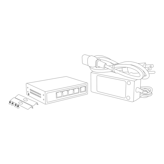
- Page 2 Installation Instructions VidaPower 4-Port 60W PoE Switch Optimized for VidaPower CAT5 to USB Power Adapters Important Notes: Do not use any other power supply with this PoE Switch. For optimal performance, only the included 52V, 1.25A power supply, or other factory recommended power supply equivalent, should be used. Indoor use ONLY. The PoE switch must be used only in a dry, non‐condensing environment. The included AC power cord must be plugged into a properly grounded wall outlet for safety. Do not use any 2‐prong to 3‐prong adapters. The switch must be placed on a stable surface, preferably mounted using the included bracket & screw kit. Do not leave it “dangling” and using plugged in cables as tension support. Drops, falls, and impacts experienced by the PoE switch can compromise the internal components and cause premature failure. Do not place heavy objects on top of the PoE switch. Allow at least 4 inches of clearance on all sides of the switch for heat ventilation. Overview ...
- Page 3 Installation Steps 1. Connect the power cable‘s trapezoidal plug into the External Power Supply Unit (PSU) 2. Connect the power cable into a standard wall outlet. The PSU’s LED will light up, confirming power. 3. Connect the External Power Supply’s round output plug into the PoE Switch. The PoE Switch’s “PWR” LED should now light up, confirming it is receiving power. 4. Finally, connect your CAT5/5e/6 cables’s RJ45 connectors into the respective PoE ports. Be sure NOT to plug it into the uplink port, which does NOT have PoE power. NOT a PoE Port (Uplink only) 5. At the other end of the cable, the VidaPower Adapters’s RJ45 port LED should light up, confirming there is power. The installation is now complete! Sample Wiring Diagram ...
- Page 4 LED Indicator Chart Indicator Text Description Status Illustration Power PWR Light Switch is powered Light Off Switch is powered off / not plugged in / no power PoE POE Yellow Light PoE is ready Yellow Light Off No PoE available 10/100Mbps Data* Green Light Ethernet connection is established Green Light Off Ethernet connection is unestablished Flashing Green Ethernet data transmission 10/100/1000Mbps Yellow Light Ethernet connection is established Yellow Light Off Ethernet connection is unestablished Flashing Yellow Ethernet data transmission * ‐ NOTE: The Data LED would NOT be expected to be flashing in our VidaPower installations. This is NORMAL. Troubleshooting Guide ...
Need help?
Do you have a question about the VidaPower VB-VPWR-PSW-60X4 and is the answer not in the manual?
Questions and answers