Advertisement
Quick Links
Advertisement

Related Manuals for MSI MS-6507 v2.X


Summary of Contents for MSI MS-6507 v2.X
- Page 1 MICRO-STAR INTERNATIONAL MS-6507 (v2.X) Micro ATX Mainboard Version 2.0 G52-MA00548...
- Page 2 FCC-B Radio Frequency Interference Statement Notice 1 Notice 2 VOIR LA NOTICE D’INSTALLATION AVANT DE RACCORDER AU RESEAU. Micro-Star International MS-6507 Tested to comply with FCC Standard For Home or Office Use...
- Page 3 Edition Feb. 2002 Copyright Notice MICRO-STAR INTERNATIONAL Trademarks ® ® ® ® ® ® ® Revision History Revision Revision History Date...
- Page 4 Safety Instructions CAUTION:...
- Page 5 CONTENTS Chapter 1. Getting Started ................ 1-1 Chapter 2. Hardware Setup ............... 2-1...
- Page 6 Chapter 3. AMI® BIOS Setup ..............3-1...
- Page 7 Chapter 4. AWARD® BIOS Setup ............4-1 Glossary ....................G-1...
- Page 8 Getting Started Chapter 1. Getting Started Getting Started ® ® ® TOPICS Mainboard Specification Mainboard Layout Quick Components Guide MSI Special Features...
- Page 9 Chapter 1 Mainboard Specification ® ® Chipset ® ® Main Memory Slots On-Board IDE On-Board Peripherals...
- Page 10 Getting Started Audio BIOS Dimension Mounting Others...
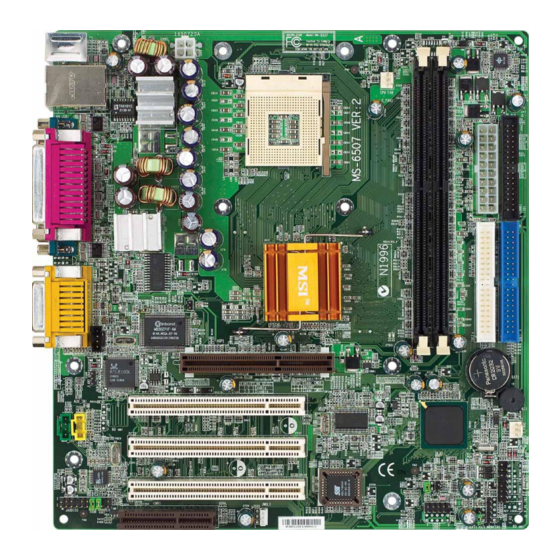
- Page 11 810 0L JLA N1 PCI Slot 1 ICH2 S_FAN1 PCI Slot 2 PCI Slot 3 Cod ec JG S 1 F_P 2 US B3 JG L 1 JAU DIO 1 JWO L1 JBAT1 JM DM 1 MS-6507 v2.X Micro ATX Mainboard...
- Page 12 Getting Started Quick Components Guide...
- Page 13 Chapter 1 MSI Special Features PC Alert™ III Note: Items shown on PC Alert III vary depending on your system’s status.
- Page 14 Hardware Setup Chapter 2. Hardware Setup Hardware Setup TOPICS Central Processing Unit: CPU Memory Power Supply Back Panel Connectors 2-13 Jumpers 2-24 Slots 2-26...
- Page 15 Chapter 2 Central Processing Unit: CPU ® ® make sure the CPU has a heat sink and a cooling fan attached on the top to prevent overheating. Open Lever Sliding Plate Gold Arrow Close Lever Overheating will seriously damage the CPU and system, always make sure the cooling fan can work properly to protect the CPU from overheating.
- Page 16 Hardware Setup Locate the CPU and its retention Position the heatsink onto the reten- mechanism on the motherboard. tion mechanism. retention mechanism Mount the fan on top of the heatsink. Press the two levers down to fasten Press down the fan until its four clips the fan.
- Page 17 Chapter 2 Connect the fan power cable from the mounted fan to the 3-pin fan power connector on the board. fan power cable then Overclocking This motherboard is designed to support overclocking. However, please make sure your components are able to tolerate such abnormal setting, while doing overclocking.
- Page 18 Hardware Setup Memory PC1600 or PC2100 Note: The DDR DIMM slots DO NOT support PC2700 modules. PC2700 PC2100 PC1600 (DDR333) (DDR266) (DDR200) Clock 166MHz 133MHz 100MHz Peak Bandwidth 2666MB/s 2133MB/s 1600MB/s...
- Page 19 Chapter 2 Slot M emory M odule Total M emory Slot 1 64MB, 128MB, 64MB~1GB (Bank 0 & Bank 1) 256MB, 512MB, 1GB Slot 2 64MB, 128MB, 64MB~1GB (Bank 2 & Bank 3) 256MB, 512MB, 1GB 64M B~2GB M aximum System M emory Supported notch Volt...
- Page 20 Hardware Setup Power Supply instant power on CONN1 Pin Definition SIGNAL SIGNAL JPW1 Pin Definition SIGNAL...
- Page 21 Chapter 2 Back Panel ® ® ® Pin Definition SIGNAL DESCRIPTION...
- Page 22 Hardware Setup ® ® ® Pin Definition SIGNAL DESCRIPTION USB Port Description SIGNAL DESCRIPTION...
- Page 23 Chapter 2 Pin Definition SIGNAL DESCRIPTION Line Out Line In 1/8” Stereo Audio Connectors 2-10...
- Page 24 Hardware Setup Pin Definition SIGNAL DESCRIPTION 2-11...
- Page 25 Chapter 2 Pin Definition SIGNAL DESCRIPTION 2-12...
- Page 26 Hardware Setup Connectors ® CINTRU 2-13...
- Page 27 Chapter 2 IDE1 IDE2 If you install two hard disks on cable, you must configure the second drive to Slave mode by setting its jumper. Refer to the hard disk documentation supplied by hard disk vendors for jumper setting instructions. 2-14...
- Page 28 Hardware Setup Phone_In Mono_Out 2-15...
- Page 29 Chapter 2 SENSOR +12V C_FAN1 SENSOR +12V S_FAN1 Note: 1. Always consult the vendor for proper CPU cooling fan. 2. CPU Fan supports the fan control. You can install the PC Alert utility that will automatically control the CPU Fan speed accord- ing to the actual CPU temperature.
- Page 30 Hardware Setup ® 5VSB ® 5VSB Note: To be able to use this function, you need a power supply that provides enough power for this feature. (750 mA 5V Stand-by) 2-17...
- Page 31 Chapter 2 ® IR2 Pin Definition Signal 2-18...
- Page 32 Hardware Setup 1 to 10 ® JAUDIO1 Pin Definition (1~10) Signal Description JAUDIO1 Pin Definition (11~20) Signal Description 2-19...
- Page 33 Chapter 2 Note: To have the Line-out connector on the back panel work properly, you need to place jumpers on pin# 13~16 (MSI spec) or on pin#5~6 and 9~10 (Intel spec) of the JAUDIO1 connector. Otherwise, this Line-out connector will not function and nothing can be heard through speakers or headphones attached to the Line-out connector on the back panel.
- Page 34 Hardware Setup ® (Intel spec) F_P2 Pin Definition SIGNAL DESCRIPTION 2-21...
- Page 35 Chapter 2 ® (Intel spec) USB3 Pin Definition Description Description 2-22...
- Page 36 Hardware Setup PLED2 PLED1 Green Color Green Color Orange Color Orange Color 2-23...
- Page 37 Chapter 2 Jumpers Clear CMOS Keep CMOS You can clear CMOS by shorting 2-3 pin while the system is off. Then return to 1-2 pin position. Avoid clearing the CMOS while the system is on; it will damage the mainboard. 2-24...
- Page 38 Hardware Setup Enable Disable Enable Disable (OPEN) (SHORT) 2-25...
- Page 39 Chapter 2 Slots 1.5V 4x 2-26...
- Page 40 Hardware Setup Order 1 Order 2 Order 3 Order 4 PCI Slot 1 INT A# INT B# INT C# INT D# PCI Slot 2 INT B# INT C# INT D# INT A# PCI Slot 3 INT C# INT D# INT A# INT B# 2-27...
- Page 41 BIOS Setup ® Chapter 3. AMI BIOS Setup ® BIOS Setup ® ®...
- Page 42 Chapter 3 Entering Setup DEL:Setup F11:Boot Menu F12:Network boot TAB:Logo Selecting the First Boot Device Select First Boot Device Floppy : 1st Floppy IDE-0 : IBM-DTLA-307038 CDROM : ATAPI CD-ROM DRIVE 40X M [Up/Dn] Select [RETURN] Boot [ESC] cancel...
- Page 43 BIOS Setup ® Control Keys Move to the previous item <↑> Move to the next item <↓> Move to the item in the left hand <←> <→> Move to the item in the right hand <Enter> Select the item <Esc> Jumps to the Exit menu or returns to the main menu from a submenu <+/PU>...
- Page 44 Chapter 3 The Main Menu ®...
- Page 45 BIOS Setup ®...
- Page 46 Chapter 3 Standard CMOS Features...
- Page 47 BIOS Setup ®...
- Page 48 Chapter 3 Advanced BIOS Features...
- Page 49 BIOS Setup ® Note...
- Page 50 Chapter 3 Option Description Setup The password prompt appears only when end users try to run Setup. Always A password prompt appears every time when the computer is powered on or when end users try to run Setup. ® ® 3-10...
- Page 51 BIOS Setup ® 3-11...
- Page 52 Chapter 3 Advanced Chipset Features Note: 3-12...
- Page 53 BIOS Setup ® 3-13...
- Page 54 Chapter 3 Power Management Setup 3-14...
- Page 55 BIOS Setup ® 3-15...
- Page 56 Chapter 3 Note 3-16...
- Page 57 BIOS Setup ® PNP/PCI Configurations 3-17...
- Page 58 Chapter 3 Data read or written by the CPU is only directed to the PCI VGA device’s palette registers. Data read or written by the CPU is directed to both the PCI VGA device’s palette registers and the ISA VGA device’s palette registers, permitting the palette registers of both VGA devices to be identical.
- Page 59 BIOS Setup ® Integrated Peripherals 3-19...
- Page 60 Chapter 3 3-20...
- Page 61 BIOS Setup ® 3-21...
- Page 62 Chapter 3 Hardware Monitor Setup 3-22...
- Page 63 BIOS Setup ® 3-23...
- Page 64 Chapter 3 Load Fail-Safe/Optimized Defaults 3-24...
- Page 65 BIOS Setup ® Supervisor/User Password About Supervisor Password & User Password: 3-25...
- Page 66 Chapter 3 IDE HDD AUTO Detection 3-26...
- Page 67 AWARD BIOS Setup ® Chapter 4. AWARD BIOS Setup ® AWARD BIOS Setup ® ®...
- Page 68 Chapter 4 Entering Setup Press DEL to enter SETUP Control Keys < ↑ > Move to the previous item < ↓ > Move to the next item < ← > Move to the item in the left hand < → > Move to the item in the right hand <Enter>...
- Page 69 AWARD BIOS Setup ® Getting Help ↑↓ ) ↑↓ )
- Page 70 Chapter 4 The Main Menu ®...
- Page 71 AWARD BIOS Setup ®...
- Page 72 Chapter 4 Standard CMOS Features...
- Page 73 AWARD BIOS Setup ®...
- Page 74 Chapter 4 Advanced BIOS Features...
- Page 75 AWARD BIOS Setup ®...
- Page 76 Chapter 4 4-10...
- Page 77 AWARD BIOS Setup ® ® 4-11...
- Page 78 Chapter 4 Advanced Chipset Features Note: 4-12...
- Page 79 AWARD BIOS Setup ® 4-13...
- Page 80 Chapter 4 Integrated Peripherals 4-14...
- Page 81 AWARD BIOS Setup ® 4-15...
- Page 82 Chapter 4 4-16...
- Page 83 AWARD BIOS Setup ® 4-17...
- Page 84 Chapter 4 Power Management Setup 4-18...
- Page 85 AWARD BIOS Setup ® 4-19...
- Page 86 Chapter 4 4-20...
- Page 87 AWARD BIOS Setup ® 4-21...
- Page 88 Chapter 4 PNP/PCI Configurations ® 4-22...
- Page 89 AWARD BIOS Setup ® ® Ø Disabled Data read or written by the CPU is only directed to the PCI VGA device’s palette registers. Enabled Data read or written by the CPU is directed to both the PCI VGA device’s palette registers and the ISA VGA device’s palette registers, permitting the palette registers of both VGA devices to be identical.
- Page 90 Chapter 4 PC Health Status 4-24...
- Page 91 AWARD BIOS Setup ® Frequency/Voltage Control 4-25...
- Page 92 Glossary Glossary Glossary ACPI Advanced Configuration & Power Interface AGP Accelerated Graphics Port BIOS basic input/output system Cache Chipset...
- Page 93 Glossary CMOS complementary metal-oxide semiconductor DIMM dual in-line memory module SIMM (single in-line memory module) DRAM Dynamic RAM Dynamic RAM (DRAM) Memory Technologies Peak Type First Used Clock Rate Bus* Width Volts Bandwidth FPM (60,70ns) 1990 25MHz 64 bits 200 MBps EDO (50,60,70ns) 1994 40MHz...
- Page 94 Glossary ECC Memory error correcting code memory IDE Integrated Drive Electronics IEEE 1394 FireWire iLink IrDA Infrared Data Association LAN local area network LED light emitting diode LPT line printer terminal...
- Page 95 Glossary PCI Peripheral Component Interconnect PnP Plug and Play POST Power On Self Test PS/2 Port USB universal serial bus Virus...
Need help?
Do you have a question about the MS-6507 v2.X and is the answer not in the manual?
Questions and answers