
Related Manuals for Vulcan-Hart Express Series


Summary of Contents for Vulcan-Hart Express Series
- Page 1 non-sto p hot water This water- heater must be installed and serviced by an authorised person. · Owners Guide and Installation Instructions. VULCAN ress n1 ____ 1--··~ �t...:_ - .. :.. l - ••. :�t... t...�--��l-..�l..l��...
- Page 2 CONTENTS About y our water heater ..........4-5 Save a service call ............. 6 Installation ..............7-14 Water p ressure ..............7 Dimensions ..............8-9 Fluein g ................· Freeze p rotection ............11 Commissionin g ............... 11 Connections ..............11 Li g htin g the heater ............
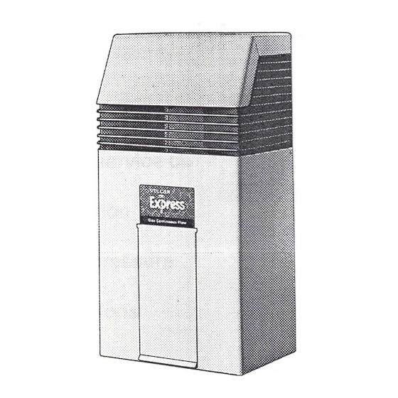
- Page 3 ABOUT YOUR WATER HEATER MODEL TYPE Congratulations for choosing a Vulcan Continuous Flow gas water heater. The model you have chosen is either an internal only or external only, and both are designed for wall mounting. The internal model has a white enamel finish and the external model has a beige colorbond outer casing with a built in balanced flue.
- Page 4 ABOUT YOUR WATER HEATER HOW LONG WILL THE WATER HEATER LAST? There are a number of factors that_ will affect the length of service th� heater will provide. These include the water quality, the water pressure and temperature (inlet and outlet) and the water usage pattern. However, your Vulcan water heater is supported by a comprehensive warranty.
- Page 6 INSTALLATION- THIS APPLIANCE IS NOT SUITABLE FOR POOL HEATING. CHECK THAT THE APPLIANCE IS SUITABLE FOR THE GAS AVAILABLE. (See appliance rating plate). The installation must comply with these installation instructions and with requirements of AS3500.4, AG601 and any other statutory requirements. In New Zealand, the installation must conform with NZS5261 Code of Practice for Installation of Gas Burning Appliances and the New Zealand Building Code.
- Page 7 INSTALLATION CAPACITY MODEL NO. 220010NO 10L/MIN. 6 � 220010PO 220013NO 13L/MIN. � 220013PO �------- ¢E 1 · · 1 CT]_ INTERNAL MODELS DIMENSIONS...
- Page 8 INSTALLATION � �I � �e a:: I ◄ -� ..40 0 27 5 27 5 ¢10 2 CUTOUTS AS DETAILED ..¢18 CUTOUT DETAIL (SCALE: 1: 5) MODELS: 23001 ONO 23001 OPO 1 OL/MIN. 230013NO 230013PO 13L/MIN. CONNECTIONS: R1/2" / 15 COLD WATER INLET HOT WATER OUTLET R1/2 /15...
- Page 9 INSTALLATION INTERNAL MODELS The location chosen for the appliance must permit the provision of a satisfactory flue and adequate air supply. The location must also provide adequate space for servicing and air circulation around the appliance. A clearance of 25mm is required at the sides and 200mm at the bottom of the appliance.
- Page 10 INSTALLATION Fluelng The external model operates on the balanced flue principle and no further flueing is required. Freeze Protection In areas where freeze conditions are likely to occur a drain cock should be fitted in the cold water line between the gate valve and the heater. The householder should be instructed on the process of draining the heater.
- Page 11 INSTALLATION Typical installation in tern al Flue ------ Flue sleeve t---___.,f11'1{;1"'--u-==4--1-I---- Burn er pressure test point Union Gate valve Hot water out --- -- --- - Isolating Pressure valve limiting valve Gas supply...
- Page 12 INSTALLATION T yp i ca I in st a 11 a ti on ·external Cold water supply branched to remainder of property Unions Cold water supply Gas cock Pressure Gate valve limiting valve Gas supply branched to remainder of property Gas supply...
- Page 13 INSTALLATION EXTERNAL MODELS -REMOVAL OF CABINET FOR SERVICE Remove the screws holding the jacket, gently spring return edges from back plate and pull forward to disengage from the terminal grill. GAS PRESSURE ADJUSTMENT NATURAL GAS MODELS ONLY Locate burner pressure test point on main burner manifold and connect manometer.
- Page 14 LIGHTING INSTRUCTIONS 1. Ensure gas and water isolating valves are fully open. 2. Fit front cover to internal models. Remove access door from external models. 3. To light the pilot rotate gas control knob to "OFF" and wait 5 minutes for escape of any unburnt gas.
- Page 15 INSTALLATION --- 2 HOLES x ,10 FOR BOLTS AND 5mm. THICK SPACERS TO ALLOW AIR GAP BETV.£EN SHIELD AND HEATER WATER --------•-------- '- - - - - - - - ,- - - - - - - -'-·t-<+6·1-------,. 49 0 ---------,k--------- ---+Q-f-- - ---r ________ ------4--4-.,.L..__ _______ _...
- Page 16 MATERIAL: GAL. OR ZINCALUME SHEET x 0.8mm. MIN. THICKNESS. HEAT SHIELD OUTDOOR - DIMENSIONS FOR USE WHEN INSTALLING HEATER ON COMBUSTIBLE SURF ACE...
- Page 17 INSTALLATION Typical installation - two temperature requirement Cold water supply Cold water supply branched to remainder of CONTINUOUS property FLOW Isolating GAS WATER HEATER valve To Kitchen & laundry Cold water Pressure supply valve limiting valve To bathroom & ensuite Tempering valve Schematic Diagram...
- Page 18 VULCAN CONTINUOUS FLOW WATER HEATER WARRANTY (AUSTRALIA ONLY) The Trade Practices Act 197 4 and similar laws in each state and territory provide the Owner under certain circumstances with remedies in the event that a Vulcan Continuous Flow Water Heater fails due to defective materials or workmanship. In addition, Southcorp Water Heater* makes the following promise: We will repair, or if necessary, replace a defective Vulcan Continuous Flow Water Heater on the following terms and conditions.
Need help?
Do you have a question about the Express Series and is the answer not in the manual?
Questions and answers