Table of Contents
Advertisement
Quick Links
Owner's Guide
and
Installation Instructions
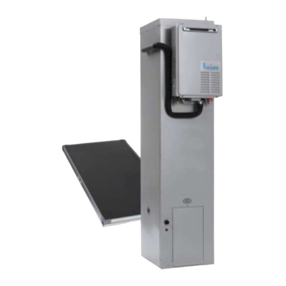
Solar VSi Storage Tank
Gas Boosted
WARNING: Plumber – Be Aware
Use copper pipe ONLY. Plastic pipe MUST NOT be used.
It is a requirement of a solar water heater installation that all pipe work be in
copper and not plastic, due to the effects of high water temperatures.
This water heater must be installed and serviced by a qualified person.
Please leave this guide with the householder.
Advertisement
Table of Contents

Subscribe to Our Youtube Channel
Related Manuals for Vulcan-Hart VSI


Summary of Contents for Vulcan-Hart VSI
- Page 1 Owner’s Guide Installation Instructions Solar VSi Storage Tank Gas Boosted WARNING: Plumber – Be Aware Use copper pipe ONLY. Plastic pipe MUST NOT be used. It is a requirement of a solar water heater installation that all pipe work be in copper and not plastic, due to the effects of high water temperatures.
- Page 2 WARNING: Plumber – Be Aware The solar hot and solar cold pipes between the solar storage tank and the solar collectors MUST BE of copper. All compression fittings must use brass or copper olives. The full length of the solar hot and solar cold pipes MUST BE insulated. The insulation must: ...
-
Page 3: Table Of Contents
CONTENTS HOUSEHOLDER – We recommend you read pages 4 to 20. The other pages are intended for the installer but may be of interest. About Your Water Heater ......................4 Regular Care ..........................11 Water Supplies ........................... 14 Save A Service Call ........................17 Installation –... -
Page 4: About Your Water Heater
® Your Vulcan indirect solar VSi water heater is designed for the solar collector to be roof mounted and the solar storage tank to be installed at ground or floor level. The solar storage tank and integrated in-series gas booster is suitable for outdoor installation only and with either one only Rheem T200 or two only Rheem NPT200, HBT200 or TBT200 solar collectors. - Page 5 ABOUT YOUR WATER HEATER MAINS PRESSURE The water heater is designed to operate at mains pressure by connecting directly to the mains water supply. If the mains supply pressure in your area exceeds that shown on page 24, a pressure limiting valve must be fitted.
- Page 6 ABOUT YOUR WATER HEATER WARNING This water heater is only intended to be operated by persons who have the experience or the knowledge and the capabilities to do so. This water heater is not intended to be operated by persons with reduced physical, sensory or mental capabilities i.e.
- Page 7 ABOUT YOUR WATER HEATER PIPE WORK AND INSULATION The solar hot and solar cold pipes between the solar storage tank and the solar collectors MUST BE of copper. The full length of the solar hot and solar cold pipes MUST BE insulated. The insulation must: be of a closed cell type or equivalent, suitable for a solar water heating application and capable of withstanding the temperatures of the fluid generated by the solar collectors under stagnation conditions be at least 13 mm thick, however thicker insulation may be required to comply with the requirements of...
- Page 8 ABOUT YOUR WATER HEATER SOLAR MONITOR The solar storage tank incorporates a solar monitor. The solar monitor is located above the lower front cover and houses both a green and a red LED. The green LED, marked “Solar”, indicates the current operational mode of the solar water heater and the red LED, marked “Attention”, indicates a fault mode.
- Page 9 ABOUT YOUR WATER HEATER TO TURN OFF THE WATER HEATER If you plan to be away from home for a few nights, we suggest you leave the water heater switched on. If it is necessary to turn off the water heater: Switch off the electrical supply at the power outlets to the solar storage tank and to the in-series gas booster if there is no risk of freezing conditions occurring (refer to note below).
- Page 10 ABOUT YOUR WATER HEATER GOING ON HOLIDAYS It is not necessary to switch off the electrical supply at the power outlets to the solar storage tank and in- series gas booster if you are going away. However, if it is necessary to switch off the power to the water “To Turn Off The Water Heater”...
-
Page 11: Regular Care
REGULAR CARE GENERAL MAINTENANCE The jacket of the gas booster can be cleaned with a soft cloth and warm mild soapy water. Under no circumstances should abrasive materials or powders be used. The area around the gas booster can be sprayed with insecticide to rid the area of insects. Insects encroaching into or nesting in the water heater can interfere with the operation of the gas booster and also damage components. - Page 12 REGULAR CARE MAJOR FIVE YEAR SERVICE For safe and efficient operation, it is recommended a major five year service be conducted on the water heater. Warning: Servicing of a water heater must only be carried out by a qualified person. Phone Rheem Service or their nearest Accredited Service Agent.
- Page 13 REGULAR CARE TEMPERATURE PRESSURE RELIEF VALVE This valve is near the top of the water heater and is essential for its safe operation. It is possible for the valve to release a little water through the drain line during each heating period. This occurs as the water is heated and expands by approximately 1/50 of its volume.
-
Page 14: Water Supplies
WATER SUPPLIES This water heater must be installed in accordance with this advice to be covered by the Vulcan warranty. This water heater is manufactured to suit the water conditions of most public reticulated water supplies. However, there are some known water chemistries which can have detrimental effects on the water heater and its operation and / or life expectancy. - Page 15 WATER SUPPLIES ANODE INSPECTION AND REPLACEMENT The anode installed in a vitreous enamel lined steel water heater cylinder will slowly dissipate whilst protecting the cylinder. The life of the cylinder may be extended by replacing the anode. “Major Five Year Service” If the anode is not replaced during a five year service (refer to on page 12) then the maximum time after installation when the anode should be replaced is 8 years.
- Page 16 WATER SUPPLIES SATURATION INDEX (SI) SOLAR WATER HEATERS - INTEGRATED GAS BOOST (CONTINUOUS FLOW) WITHIN WARRANTY SPECIFICATION -1.0 +0.4 +0.8 SATURATION INDEX (calculated @ 80°C water temperature) scaling very corrosive corrosive very scaling SUMMARY OF WATER CHEMISTRY ADVICE AFFECTING WARRANTY The water heater, solar collectors and their components are not suitable for certain water chemistries.
-
Page 17: Save A Service Call
SAVE A SERVICE CALL Check the items below before making a service call. You will be charged for attending to any condition or fault that is not related to manufacture or failure of a part. COLD WATER FROM THE HOT TAP Close the hot tap, wait 10 seconds and open the hot tap again. - Page 18 SAVE A SERVICE CALL GAS BOOSTER OPERATING TOO FREQUENTLY You may find that the in-series gas booster operates more frequently than expected. This will occur when the solar heated water temperature is lower than 58°C, which may be experienced during periods of low solar energy gain or if there has been heavy hot water usage.
- Page 19 SAVE A SERVICE CALL COLLECTOR GLASS The Vulcan warranty DOES NOT cover breakage of solar collector glass. Check your household insurance policy covers collector glass breakage. Warning: No attempt should be made to remove or replace broken collector glass. The collector glass is not offered as a replacement part. Should the solar collector require replacement, contact Rheem Service or their nearest Accredited Service Agent.
- Page 20 SAVE A SERVICE CALL ERROR CODE The in-series gas booster provides a diagnostic error code in the event of an interruption to its operation. The error code is displayed on the front of the in-series gas booster on the OK MONITOR as a series of flashes. If an error code appears: Close the hot tap and switch off the electrical supply to the in- series gas booster.
-
Page 21: Installation - Solar Storage Tank
INSTALLATION – SOLAR STORAGE TANK THIS WATER HEATER IS FOR OUTDOOR INSTALLATION ONLY. THIS WATER HEATER IS NOT SUITABLE FOR POOL HEATING. Check the water heater is suitable for the gas type available. (refer to the rating label on the water heater) The system is suitable for installation with either one Rheem T200 or two Rheem NPT200 or HBT200 solar collectors. - Page 22 INSTALLATION – SOLAR STORAGE TANK Victorian Installers Notice to Victorian Installers from the Victorian Plumbing Industry Commission if this solar water heater is installed in a new Class 1 dwelling in the State of Victoria. The system model number is to be recorded on the Certificate of Compliance.
- Page 23 INSTALLATION – SOLAR STORAGE TANK The water heater must be located to ensure that the location of the flue terminal complies with the requirements of AS 5601 or AS/NZS 5601.1, as applicable under local regulations. As a guide the following requirements are extracted from the Gas Installations Standard.
- Page 24 INSTALLATION – SOLAR STORAGE TANK MAINS WATER SUPPLY Where the mains water supply pressure exceeds that shown in the table below, an approved pressure limiting valve is required and should be fitted as shown in the installation diagram (refer to diagram on page 36).
- Page 25 INSTALLATION – SOLAR STORAGE TANK RAIN WATER TANK If the solar collector and solar pipe work are to be installed on a section of roof which is part of a rain water runoff collection system, then it is recommended this section of roof and its gutter be isolated from the rain water collection system.
- Page 26 INSTALLATION – SOLAR STORAGE TANK HOT WATER DELIVERY This water heater can deliver water at temperatures which can cause scalding. It is necessary and we recommend that a temperature limiting device be fitted between the water heater and the hot water outlets in any ablution area such as a bathroom or ensuite, to reduce the risk of scalding. The installing plumber may have a legal obligation to ensure the installation of this water heater meets the delivery water temperature requirements of AS/NZS 3500.4 so that scalding water temperatures are not delivered to a bathroom, ensuite or other ablution area.
- Page 27 INSTALLATION – SOLAR STORAGE TANK CIRCULATED HOT WATER FLOW AND RETURN SYSTEM A solar water heater should not be installed as part of a circulated hot water flow and return system in a building. The benefits of solar gain will be significantly reduced and energy gained from the sun lost through the pipe work.
- Page 28 INSTALLATION – SOLAR STORAGE TANK REDUCING HEAT LOSSES The cold water line to and the hot water line from the water heater must be insulated in accordance with the requirements of AS/NZS 3500.4. The insulation must be weatherproof and UV resistant if exposed. The full length of the solar hot and solar cold pipes between the solar storage tank and the solar collector(s) “Warning: Plumber Be Aware”...
- Page 29 INSTALLATION – SOLAR STORAGE TANK DIMENSIONS AND TECHNICAL DATA Solar Connections Solar Solar Preheat Preheat Valve Outlet Outlet Water Outlet Cold Cold Water Water Inlet Inlet storage tank Storage Tank with Storage Tan with integrated in-series gas booster Integrated Gas Boost (Remote Boo Model 696 160...
- Page 30 INSTALLATION – SOLAR STORAGE TANK TYPICAL INSTALLATION – OUTDOOR LOCATION SENSOR CONNECTION HOT SENSOR LEAD SOLAR COLD PIPE Insulated copper pipe.Use a compression nut and olive. CABLE TIE TO PIPE INSULATION SOLAR HOT PIPE Insulated copper pipe. TEMPERATURE Use a compression PRESSURE nut and olive.
-
Page 31: Installation - Solar Collector
INSTALLATION – SOLAR COLLECTOR SOLAR COLLECTOR LOCATION Consideration must be given to the position of the solar collector in relation to the solar storage tank. There are limitations on both the maximum length of the solar hot and solar cold pipes and the maximum height “Solar Storage Tank Location”... - Page 32 INSTALLATION – SOLAR COLLECTOR LATITUDE OF SOME AUSTRALIAN CITIES Adelaide 35°S Cairns 17°S Hobart 42°S Port Hedland 20°S Alice Springs 24°S Canberra 35°S Mildura 34°S Rockhampton 24°S Brisbane 27°S Darwin 12°S Melbourne 38°S Sydney 34°S Broken Hill 31°S Geraldton 28°S Perth 32°S Townsville...
- Page 33 INSTALLATION – SOLAR COLLECTOR WARNING: Plumber – Be Aware The solar hot and solar cold pipes between the solar storage tank and the solar collectors MUST BE of copper. All compression fittings must use brass or copper olives. The full length of the solar hot and solar cold pipes MUST BE insulated. The insulation must: ...
- Page 34 INSTALLATION – SOLAR COLLECTOR Maximum Height To Collector The solar collector(s) must be the highest point of the system. The maximum height of the solar installation, from the base of the solar storage tank to the top of the solar collector(s), is 7.5 m. The pump supplied with the solar storage tank will not circulate closed circuit fluid through heights greater than 7.5 m and solar gain will not be achieved.
- Page 35 INSTALLATION – SOLAR COLLECTOR Pressure Testing The solar water heater, including the collector circuit and solar collectors, is to be isolated during the testing and commissioning of the heated water reticulation system in a building, in accordance with Clause 11.1 and 11.3 (a) of AS/NZS 3500.4.
-
Page 36: Connections - Plumbing
CONNECTIONS – PLUMBING All plumbing work must be carried out by a qualified person and in accordance with the requirements of the Standard AS/NZS 3500.4, and all local codes and regulatory authority requirements. In New Zealand, the installation must conform with Clause G12 of the New Zealand Building Code. All gas work must be carried out by a qualified person and in compliance with the Standard AS 5601 or AS/NZS 5601.1, as applicable under local regulations, and all local codes and regulatory authority requirements. - Page 37 CONNECTIONS – PLUMBING PIPE SIZES To achieve true mains pressure operation, the cold water line to the water heater should be the same size or bigger than the hot water line from the water heater. The minimum recommended hot pipe size is DN20. The pipe sizing for hot water supply systems should be carried out by persons competent to do so, choosing the most suitable pipe size for each individual application.
- Page 38 CONNECTIONS – PLUMBING TEMPERATURE PRESSURE RELIEF VALVE The temperature pressure relief valve is shipped behind the lower front cover of the water heater. The temperature pressure relief valve must be fitted before the water heater is operated. Before fitting the relief valve, make sure the probe has not been bent.
- Page 39 CONNECTIONS – PLUMBING SOLAR INLET AND OUTLET All pipe work must be cleared of foreign matter before connection and purged before attempting to operate the water heater. All olive compression fittings must use brass or copper olives. Use thread sealing tape or approved thread sealant on all fittings.
- Page 40 CONNECTIONS – PLUMBING GAS INLET The gas connection is made at the underside of the in- series gas booster. The pipe work must be cleared of foreign matter before connection and purged before attempting to operate the water heater. An isolation valve and disconnection union must be installed to allow servicing and removal of the water heater.
-
Page 41: Connections - Electrical
CONNECTIONS – ELECTRICAL The power supply to the water heater must not be switched on until the solar storage tank is filled with water. MEGGER READING It is not mandatory to conduct a megger test on a plug in appliance, however if a megger test is conducted on this water heater, then the following should be noted. - Page 42 CONNECTIONS – ELECTRICAL HOT SENSOR LEAD The plug on the hot sensor lead connected to the solar control board, located behind the front cover of the solar storage tank, is to be connected to the socket on the hot sensor from the solar collector. To connect the hot sensor leads together: Feed the hot sensor lead from the solar CONNECT PLUG AND...
- Page 43 CONNECTIONS – ELECTRICAL WIRING DIAGRAM Wiring Diagram Solar Drain Back Integrated Gas Boost & Storage Tank...
-
Page 44: Commissioning
COMMISSIONING TO FILL AND TURN ON THE WATER HEATER The power supply to the water heater must not be switched on until the solar storage tank is filled with water. To fill the solar storage tank with water and turn on the water heater: Open all of the hot water taps in the house (don‟t forget the shower). - Page 45 COMMISSIONING SOLAR CIRCUIT Commissioning of the Solar Circuit It is necessary to commission and check the operation of the solar circuit as part of the installation. The water heater is supplied charged with closed circuit fluid. The commissioning procedure includes checking the: circulation of closed circuit fluid through the solar circuit.
- Page 46 COMMISSIONING PRE-COMMISSIONING WARNINGS It is recommended to conduct the solar circuit commissioning procedure with the solar collector covered, otherwise during the commissioning and checking procedure of the solar circuit, the closed circuit fluid may experience solar gain as it passes through the solar collector. This will increase both the temperature and pressure of the closed circuit fluid and vapour inside of the solar circuit.
- Page 47 COMMISSIONING Commissioning the Solar Circuit To commission and check the solar circuit: Switch off the electrical supply at the power outlets to the solar storage tank and in-series gas booster. If the pump has been operating, wait five minutes to allow the drain back of the closed circuit fluid in the solar circuit.
- Page 48 COMMISSIONING Solar Circuit Circulation Disconnect the hot sensor lead from the solar control board inside of the lower front cover of the solar storage tank. It is important, at the end of this procedure when the commissioning and checking of the solar circuit is complete, to reconnect the hot sensor lead, otherwise when the electrical supply is switched on, the solar pump will deactivate after one hour and the solar control unit...
- Page 49 COMMISSIONING Mark the dynamic level of the closed circuit fluid in the mark dynamic hose on the side of the solar storage tank with a non level on tank permanent marker when satisfied the solar circuit circulation is operating satisfactorily. If the procedure to check the solar circuit circulation is not complete before the pump has automatically turned off, then:...
- Page 50 COMMISSIONING Closed Circuit Fluid Level Measure the distance from the text marking “MINIMUM FLUID LEVEL WITH PUMP OPERATING” to the closed circuit fluid dynamic level marked on the side of the solar storage tank during step The correct closed circuit fluid dynamic level for efficient operation of the system when the pump is operating, is between the “MINIMUM FLUID LEVEL WITH PUMP OPERATING”...
- Page 51 COMMISSIONING Determine the correct amount of water to be added to or closed circuit fluid to be drained from the heat exchanger if the dynamic level is either below the text marking “MINIMUM FLUID LEVEL WITH PUMP OPERATING” or more than 150 mm above this mark. Each 100 mm of fluid level height is equivalent to 730 ml (0.73 litres) of closed circuit fluid.
- Page 52 COMMISSIONING Measure into a container the amount of water to be added to top up the level of the closed circuit fluid in the heat exchanger if required. To add water to the closed circuit fluid: If not already removed, disconnect the drain line and remove the spring clip from the solar circuit ...
- Page 53 COMMISSIONING Checking the Solar Circuit for Leaks Close the heat exchanger drain valve. heat exchanger drain valve Refit the solar circuit relief valve, orientating the valve closed outlet to the rear of the solar storage tank. Secure with the spring clip. Reconnect the drain pipe to the valve. Switch on the electrical supply at the power outlet to the solar storage tank.
- Page 54 COMMISSIONING Remove Closed Circuit Fluid Level Hose Remove the clear hose from the solar storage tank when satisfied the commissioning procedure is complete. To remove the hose: Ensure the heat exchanger drain valve is closed. heat exchanger Remove the hose from the side of the storage tank ...
- Page 55 COMMISSIONING DIAGNOSTIC FEATURES OF THE SOLAR CONTROLLER The solar storage tank incorporates a solar monitor which is connected to the solar control module by a ribbon cable. The solar monitor is located above the lower front cover and houses both a green and a red LED.
- Page 56 COMMISSIONING GAS INLET PRESSURE IMPORTANT - CHECK the gas supply pressure at the inlet to the water heater with the water heater and all other gas burning appliances in the premises operating (burners alight). The minimum gas supply pressure Natural Gas 1.13 kPa Propane 2.75 kPa...
- Page 57 COMMISSIONING If an adjustment was made during Step 9, repeat this procedure from Step 5. Close the hot tap(s). Close the gas isolation valve at the inlet to the water heater. Remove the manometer and refit and tighten the test point screw. Open the gas isolation valve fully at the gas inlet to the water heater.
- Page 58 COMMISSIONING Minimum test point gas pressure Refer to the rating label on the water heater for the minimum test point gas pressure. Close any hot taps and ensure the burners are not operating. Switch off the electrical supply at the power outlet to the water heater.
- Page 59 COMMISSIONING Switch on the electrical supply at the power outlet to the water heater. Turn on the controller by pressing the on / off button. ACTIVE °C 8 8 8 8 The priority light (standard controller) or ACTIVE light BATH (l) (Deluxe controller) and the light in the on / off button will both glow.
- Page 60 COMMISSIONING Maximum test point gas pressure Refer to the rating label on the water heater for the maximum test point gas pressure. “Minimum test point gas pressure” Follow Steps 10 to 16 of the procedure on page 58, but open the hot tap fully and use the MAX button instead of the MIN button.
- Page 61 COMMISSIONING TO CHECK OR ADJUST THE PRESET OUTLET TEMPERATURE SETTING The temperature setting will be displayed by a series of flashes from the red LED, with a three (3) second pause between each series of flashes. The temperature settings and series of flashes are: 244 620 model 55°C (1 flash), 60°C (2 flashes), 70°C (3 flashes) It is necessary to have the electrical supply to the water heater switched on during stages of checking or...
- Page 62 COMMISSIONING TO TURN OFF THE WATER HEATER If it is necessary to turn off the water heater on completion of the installation, such as on a building site or where the premises is vacant, then: Switch off the electrical supply at the power outlets to the solar storage tank and in-series gas booster (refer to note below).
-
Page 63: Draining The Water Heater
DRAINING THE WATER HEATER GAS BOOSTER WATER HEATER To drain the in-series gas booster: “To Turn Off The Water Heater” Turn off the water heater (refer to on page 62). Open a hot tap (preferably the shower outlet). Unscrew the two drain plugs, one each at the cold water inlet and hot water outlet, on the underside of the in-series gas booster. - Page 64 DRAINING THE WATER HEATER HEAT EXCHANGER Warning: Exercise care, as fluid discharged from the heat exchanger may be of a very high temperature. To drain the closed circuit heat exchanger: Switch off the electrical supply at the power outlet to the solar storage tank. Remove the lower front cover from the solar storage tank.
- Page 65 This page is intentionally blank.
- Page 66 This page is intentionally blank.
-
Page 67: Warranty
VULCAN SOLAR WATER HEATER WARRANTY – AUSTRALIA ONLY – SOLAR WATER HEATER MODEL 596160 1. THE VULCAN WARRANTY – GENERAL This warranty is given by Rheem Australia Pty Limited ABN 21 098 823 511 of 1 Alan Street, Rydalmere New South Wales, the manufacturer of Vulcan mains pressure water heaters and the supplier of Vulcan continuous flow gas water heaters, manufactured by Paloma Co., Ltd., a world leader in water heater technology and manufacture. - Page 68 VULCAN SOLAR WATER HEATER WARRANTY – AUSTRALIA ONLY – SOLAR WATER HEATER MODEL 596160 3. WHAT IS COVERED BY THE VULCAN WARRANTY FOR THE WATER HEATERS DETAILED IN THIS DOCUMENT Rheem will repair or replace a faulty component of your water heater if it fails to operate in accordance with its specifications as follows: The period from the date of What components are covered installation in which the fault must...
Need help?
Do you have a question about the VSI and is the answer not in the manual?
Questions and answers