
Related Manuals for Mita DC-1460

Summary of Contents for Mita DC-1460
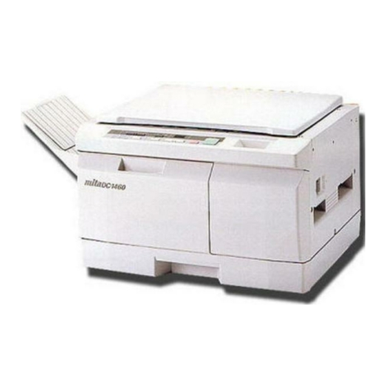
- Page 1 DC-1460 SERVICE MANUAL Published in Apr. ’98 19570762 Revision 2 DC-1460 S/M (MCA)
- Page 2 CAUTION: DOUBLE-POLE / NEUTRAL FUSING...
- Page 3 Service Manual DC-1460...
- Page 4 Safety precautions This booklet provides safety warnings and precautions for our service personnel to ensure the safety of their customers, their machines as well as themselves during maintenance activities. Service personnel are advised to read this booklet carefully to familiarize themselves with the warnings and precautions described here before engaging in maintenance activities.
- Page 5 Safety warnings and precautions Various symbols are used to protect our service personnel and customers from physical danger and to prevent damage to their property. These symbols are described below: DANGER: High risk of serious bodily injury or death may result from insufficient attention to or incorrect compliance with warning messages using this symbol.
- Page 6 indicates that action is required. The specific action required is shown inside the symbol. General action required. Remove the power plug from the wall outlet. Always ground the copier. 1. Installation Precautions WARNING • Do not use a power supply with a voltage other than that specified. Avoid multiple connections to one outlet: they may cause fire or electric shock.
- Page 7 • Always handle the machine by the correct locations when moving it..• Always use anti-toppling and locking devices on copiers so equipped. Failure to do this may cause the copier to move unexpectedly or topple, leading to injury................•...
- Page 8 • Check that the power cable covering is free of damage. Check that the power plug is dust-free. If it is dirty, clean it to remove the risk of fire or electric shock..................• Never attempt to disassemble the optical unit in machines using lasers. Leaking laser light may damage eyesight.
- Page 9 • After maintenance, always check that all the parts, screws, connectors and wires that were removed, have been refitted correctly. Special attention should be paid to any forgotten connector, trapped wire and missing screws..................• Check that all the caution labels that should be present on the machine according to the instruction handbook are clean and not peeling.
-
Page 10: Table Of Contents
195-1 CONTENTS THEORY AND CONSTRUCTION SECTION 1-1 Specifications 1-1-1 Specifications ................... 1-1-1 1-2 Handling Precautions 1-2-1 Drum ....................1-2-1 1-2-2 Developer and toner ................. 1-2-1 1-3 Mechanical Construction 1-3-1 Part names and their functions ............1-3-1 1-3-2 Machine cross section ..............1-3-3 1-3-3 Drive system .................. - Page 11 195-1 3-4 PCB Initial Setting 3-4-1 Replacing the main PCB ..............3-4-1 3-4-2 Adjustment-free variable resistors (VR) ........... 3-4-3 3-5 Self-diagnostics 3-5-1 Self diagnostic function ..............3-5-1 3-6 Troubleshooting 3-6-1 Image formation problems ..............3-6-1 3-6-2 Paper misfeed ................3-6-15 3-6-3 PCB terminal voltages ..............
-
Page 12: Itheory And Construction Section
THEORY AND CONSTRUCTION SECTION DC-1460 S/M (MCA) -
Page 13: Specifications
1-1 Specifications 1-1-1 Specifications ..................1-1-1... - Page 14 1-1-1 Specifications Type ......... Desktop Copying system ....... Dry, indirect electrostatic system Originals ........Sheets, books and 3-dimensional objects " × 14" Maximum size: Folio/8 Original feed system ....Fixed Copy paper ......Plain paper: 80 g/m (metric), 75 g/m (inch) for drawer feed 60 - 120 g/m (metric), 75 g/m...
- Page 15 Fixing system ......Heat roller Heat source: halogen heater (910 W with 120 V supply, 1040 W with 240 V supply) Control temperature: 175°C/347°F (at normal ambient temperature) Abnormally high temperature protection devices: 135°C/275°F and 140°C/284°F thermostats Fixing pressure: 94 N Charge erasing system ....
-
Page 16: Handling Precautions
1-2 Handling Precautions 1-2-1 Drum ....................1-2-1 1-2-2 Developer and toner ................1-2-1... -
Page 17: Drum
1-2-1 Drum Note the following when handling or storing the drum. • When removing the drum unit, never expose the drum surface to strong direct light. • Keep the drum at an ambient temperature between –20°C/–4°F and 40°C/104°F and at a relative humidity not higher than 85% RH. Avoid abrupt changes in temperature and humidity. -
Page 18: Mechanical Construction
1-3 Mechanical Construction 1-3-1 Part names and their functions ............1-3-1 1-3-2 Machine cross section ............... 1-3-3 1-3-3 Drive system ..................1-3-4 1-3-4 Mechanical construction ..............1-3-5 ( 1 ) Paper feed section ..............1-3-5 (1-1) Paper feed from the paper drawer ........1-3-7 (1-2) Paper feed from the bypass slot ........ -
Page 19: Part Names And Their Functions
1-3-1 Part names and their functions & ⁄ Figure 1-3-1 1 Original holder 9 Front cover & Bypass section 2 Contact glass 0 Paper drawer * Insertion guides 3 Original size indicator ! Main switch ( Release unit 4 Operation panel @ Grips ) Release unit button 5 Drum unit... - Page 20 Metric 1 Print key 2 Copy start indicator & % 3 Stop/clear key 4 Quantity/zoom-up key 5 Quantity/zoom-down key 6 Copy quantity/magnification display 7 Zoom input/enter key 8 Zoom copy indicator 9 Copy size key 0 Fixed magnification indicators ! Add toner indicator @ Maintenance indicator (metric) Replace unit indicator (inch) # Exposure adjustment keys...
-
Page 21: Machine Cross Section
1-3-2 Machine cross section Figure 1-3-3 Machine cross section 1 Paper feed section (page 1-3-5) 5 Transfer and separation section 2 Main charging section (page 1-3-9) (page 1-3-26) 3 Exposure section (page 1-3-12) 6 Cleaning section (page 1-3-29) 4 Developing section (page 1-3-18) 7 Charge erasing section (page 1-3-30) 8 Fixing and eject section (page 1-3-32) 1-3-3... -
Page 22: Drive System
1-3-3 Drive system ¤ fi „ · ° fl › ‹ ‡ ⁄ Œ ‚ & As viewed from machine rear Figure 1-3-4 Drive system 1 Scanner wire & Feed gear 16 2 Scanner wire pulley * Gear 35 3 Mirror motor gear ( Paper feed clutch gear 4 Scanner drive gear B ) Registration gear 14... -
Page 23: Mechanical Construction
1-3-4 Mechanical construction ( 1 ) Paper feed section 5 3 2 Figure 1-3-5 Paper feed section 1 Drawer bottom plate 9 Right registration roller 2 Drawer spring 0 Left registration roller 3 Front and rear drawer claws ! Upper pre-transfer guide 4 Paper feed pulleys A and B @ Pre-transfer guide 5 Feed roller guide... - Page 24 The paper feed section consists of the primary feed and secondary feed subsections. Primary feed conveys paper from the paper drawer or the bypass slot to the right and left registration rollers, at which point secondary paper feed takes place and the paper travels to the transfer section in sync with the exposure timing.
-
Page 25: Paper Feed From The Paper Drawer
(1-1) Paper feed from the paper drawer The paper drawer consists of the drawer bottom plate, drawer springs and other components and can hold up to 250 sheets of copy paper. Paper is fed out of the drawer by the rotation of paper feed pulleys A and B. Print key HPSW 200 ms... -
Page 26: Paper Feed From The Bypass Slot
(1-2) Paper feed from the bypass slot The bypass slot can hold one sheet of paper at one time. Copying starts when the paper turns the registration switch (RSW) on and the paper is conveyed to the secondary paper feed section by the feed roller. HPSW 330 ms 246 P *... -
Page 27: 2 ) Main Charging Section
( 2 ) Main charging section The main charging section consists of the drum and main charger. The drum is electrically charged uniformly by means of a grid to form a latent image on the surface. Tungsten wire Main charger Main charger grid Figure 1-3-7 Main charging section 1-3-9... - Page 28 Figure 1-3-8 Main charger 1 Main charger rear lid 2 Charger spring 3 Charger wire 4 Main charger front lid 5 Charger wire retainer pin 24 V DC CN8-7 CN1-1 DB REM CN8-5 CN1-3 HV REM CN8-4 CN1-4 PHOTO REM Grid CN8-3 CN1-5...
- Page 29 Print key 200 ms 50 ms 384 ms HV REM " × 14" copy paper, paper feed from the paper drawer Manual exposure mode, A4R/8 Timing chart 1-3-3 Main charging A 200 ms after the print key has been pressed, the drive motor (DM) starts to rotate. B 50 ms after the drive motor (DM) has started to rotate, main charging (HV REM) starts.
-
Page 30: 3 ) Exposure Section
( 3 ) Exposure section & 87@ # 9 3 2 ! Figure 1-3-10 Exposure section 1 Mirror 1 ! Light source unit 2 2 Mirror 2 @ Main reflector 3 Mirror 3 # Auxiliary reflector 4 Mirror 4 $ Scanner motor (SM) 5 Mirror 5 % Optical section fan motor (OPFM) 6 Mirror 6... - Page 31 This copier employs a slit exposure system with a fixed original table, and a halogen lamp (HL) as the light source. The optical section consists of light source units 1 and 2. Light source unit 1 carries the halogen lamp and the main and auxiliary reflectors. Each unit travels from one side of the machine to the other along scanner rails at machine front and rear.
- Page 32 Print key 200 ms HPSW 2358 P 910 P 55 ms 350 ms 100 ms 65 ms " × 14" original Auto exposure mode, A4R/8 Timing chart 1-3-4 Scanner travel A 200 ms after the print key has been pressed, the halogen lamp (HL) lights at the intensity for prescan.
- Page 33 Exposure control for manual exposure and photo modes The halogen lamp light intensity for manual exposure and photo modes is calculated from the data obtained by running simulation 24. The number of exposure steps depends on the setting in simulation 96-1: 7 or 13 steps when set to “NORMAL MODE” and 19 or 25 steps when set to “SPECIAL AREA”.
- Page 34 Exposure control for auto exposure mode In auto exposure mode, the halogen lamp lights at the intensity set by simulation 28-1 to perform prescan. The exposure level to copy that particular original is determined by using the value read in by the AE sensor. AE detection (prescan) Original leading edge Exposure...
- Page 35 Light intensity correction for enlargement and reduction modes The halogen lamp light intensity for enlargement and reduction modes is determined by the value for copying at 100% magnification and the correction values set by simulation Light intensity correction value Sim. 29-1 (141%) Sim.
-
Page 36: 4 ) Developing Section
( 4 ) Developing section The developing section consists of the developing unit and toner cartridge. Toner cartridge Developing unit Figure 1-3-16 Developing section The developing unit consists of the developing roller where a magnetic brush is formed, doctor blade and the developing spirals that agitate the developer. Toner in the toner cartridge is mixed with residual toner recovered from the cleaning section, and the mixture is conveyed to the developing unit. - Page 37 Cleaning spiral Toner cartridge spiral Toner cartridge paddle Toner cartridge Developing unit Toner flow Toner recycling spiral Figure 1-3-17 Toner recycling 1-3-19...
- Page 38 Formation of the magnetic brush The developing roller consists of a magnet roller with five poles and a sleeve roller. Rotation of the sleeve roller around the magnet roller entrains developer, which in turn forms a magnetic brush at pole N1 on the magnet roller. The height of the magnetic brush is regulated by the doctor blade;...
- Page 39 CN2-1 CN2-2 DB REM CN8-5 CN1-3 HVTPCB Developing bias CN6-7 TNS CONT CN6-8 MPCB Figure 1-3-19 Developing section block diagram Toner density is detected by the toner sensor (TNS). The sensor section of the toner sensor detects the ratio of toner to carrier in the developer near it and converts it into a voltage.
- Page 40 195-1 Toner density control Toner density is controlled by switching the toner feed motor on and off, using as the reference the toner sensor output based on the toner sensor control voltage set when simulation 60 was executed while the developer was first supplied. The toner sensor output is also used to detect an empty toner cartridge.
- Page 41 Toner sensor output voltage (V) Toner cartridge replacement AP detection level (3.21) If forced feed does not lower the level, the add toner indicator stays lit. Toner empty Max. 3'19" end level (2.75) The add toner indicator Forced toner feed turns off and intermittent Toner feed motor on feed continues(2 minutes...
- Page 42 195-1 Controlling the toner sensor output voltage When initializing the toner control level in simulation 60, the toner sensor control voltage (TNS CONT) is set so that the toner sensor output voltage (TNS) is 1.60 V DC. The image density is subject to humidity changes and the developing unit drive time. To maintain the image density constant, the toner sensor output voltage (TNS) is corrected by the toner sensor control voltage (TNS CONT).
- Page 43 [Computing the absolute humidity] The humidity sensor (HUMSENS) and external temperature thermistor (ETTH) are located on the humidity sensor PCB (HUMPCB). The humidity sensor (HUMSENS) converts the relative humidity detected by the humidity sensing element into a voltage and sends it to the main PCB (MPCB). The main PCB computes the absolute humidity based on this HUMSENS signal and the temperature (ETTH signal) detected by the external temperature thermistor.
-
Page 44: 5 ) Transfer And Separation Section
( 5 ) Transfer and separation section Post-transfer guide Tungsten wire Transfer charger Figure 1-3-25 Transfer and separation section The transfer and separation section consists of the transfer charger. In the transfer charger, a high voltage generated by the high-voltage transformer PCB (HVTPCB) is applied across both ends of the tungsten wire for transfer charging and the toner image is transferred from the drum surface onto the paper. - Page 45 Figure 1-3-26 Transfer charger 1 Front transfer housing 6 Pre-transfer guide 2 Rear transfer housing 7 Charger wire 3 Transfer front lid 8 Charger spring 4 Transfer rear lid 9 Charger wire retainer pin 5 Transfer charger shield 24 V DC CN8-7 CN1-1 Drum...
- Page 46 Print key 200 ms 50 ms 384 ms HV REM " × 14" copy paper, paper feed from the paper drawer Manual exposure mode, A4R/8 Timing chart 1-3-5 Transfer and separation A 200 ms after the print key has been pressed, the drive motor (DM) starts to rotate. B 50 ms after the drive motor (DM) has started to rotate, transfer charging (HV REM) starts.
-
Page 47: 6 ) Cleaning Section
( 6 ) Cleaning section The cleaning section consists of the cleaning blade, which removes residual toner from the drum surface after transfer, and the cleaning spiral that carries the residual toner back to the toner cartridge. Figure 1-3-28 Cleaning section 1 Drum 3 Lower cleaning blade 2 Cleaning blade... -
Page 48: 7 ) Charge Erasing Section
( 7 ) Charge erasing section Cleaning lamp (CL) Blank lamps (BL) Figure 1-3-29 Charge erasing section The charge erasing section consists of the blank lamps (BL) and the cleaning lamp (CL). The blank lamps (BL) are 28 LEDs. All the LEDs light to create leading edge and trailing edge blank cut margins. - Page 49 Scan start HV REM 100 ms 200 ms 285 ms 127 P * 190 ms * All on Side erasure All on " × 14" copy paper, Bypass feed, manual exposure mode, A4R/8 magnification ratio 70% *1 Varies depending on the magnification ratio and the setting by simulation 54. *2 Varies depending on the setting by simulation 59.
-
Page 50: 8 ) Fixing And Eject Section
195-1 ( 8 ) Fixing and eject section & Figure 1-3-31 Fixing and eject section 1 Fixing unit cover 0 Eject pulley 2 Fixing unit upper housing ! Eject roller 3 Fixing unit lower housing @ Fixing heater (H) 4 Fixing entrance guide # Fixing unit thermostat 1 (TH1) 5 Eject guide $ Fixing unit thermostat 2 (TH2) - Page 51 The fixing and eject section consists of the parts shown in Figure 1-3-31. When the paper reaches the fixing section after the transfer process, it passes through the gap between the press roller and heat roller, which is heated by the fixing heater (H). Pressure is applied by the fixing pressure springs so that toner on the paper is melted and fused onto the paper.
- Page 52 Heating the heat roller and detecting temperature Figure 1-3-33 Heating the heat roller and detecting temperature 1 Heat roller 4 Fixing unit thermostat 2 (TH2) 2 Fixing heater (H) 5 Fixing unit thermistor (FTH) 3 Fixing unit thermostat 1 (TH1) The heat roller is heated by the fixing heater (H) inside it;...
- Page 53 Fixing temperature control 200 ms 10 s Half speed Full speed Copy start indicator 29 s Timing chart 1-3-7 Fixing temperature control A When the main switch (MSW) is turned on the fixing heater (H) turns on to heat the heat roller.
- Page 54 195-1 • Correcting the fixing temperature control The fixing temperature is changed according to the temperature detected by the external temperature thermistor (ETTH) on the humidity sensor PCB (HUMPCB). When the temperature detected by the thermistor is 32°C/89.6°F or above, the fixing temperature is 175°C/347°F during standby and 180°C/356°F during copying.
-
Page 55: Electrical Section
ELECTRICAL SECTION DC-1460 S/M (MCA) -
Page 56: Electrical Parts Layout
2-1 Electrical Parts Layout 2-1-1 Electrical parts layout ................ 2-1-1... - Page 57 2-1-1 Electrical parts layout Machine front Machine inside Machine rear Figure 2-1-1 Layout of electrical parts: PCBs 1. Main PCB (MPCB) ........Controls the other PCBs and electrical components. 2. Power source PCB (PSPCB) ....... Generates 24 V and 5 V DC; supplies AC to the AVR PCB;...
- Page 58 195-1 Machine front Machine inside Machine rear Figure 2-1-2 Layout of electrical parts: switches and sensors 1. Main switch (MSW) ........Turns the AC power on and off. 2. Safety switch (SSW) ........Breaks the safety circuit when the front cover or release unit is opened, and resets paper jam detection.
- Page 59 Machine front Machine inside Machine rear Figure 2-1-3 Layout of electrical parts: motors and clutches 1. Drive motor (DM) ......... Drives the machine. 2. Scanner motor (SM) ........Drives the optical system. 3. Lens motor (LM) .......... Drives the lens. 4.
- Page 60 5, 6 Machine front Machine inside Machine rear Figure 2-1-4 Layout of electrical parts: other electrical parts 1. Halogen lamp (HL) ........Performs exposure. 2. Cleaning lamp (CL) ........Removes residual charge from the drum surface. 3. Blank lamps (BL) ......... Remove charge from non-image forming areas of the drum surface.
-
Page 61: Detection Of Paper Misfeeds
2-2 Detection of Paper Misfeeds 2-2-1 Paper misfeed detection ..............2-2-1 2-2-2 Paper misfeed detection conditions ..........2-2-2... -
Page 62: Paper Misfeed Detection
2-2-1 Paper misfeed detection When a paper jam occurs, the copier immediately stops copying and the copy quantity/ magnification display on the operation unit shows PF, J01, J02 or J03 indicating the location of the jam. The letter J and the number alternates on the display. To remove paper jammed in the copier, open the release unit, drawer or eject section cover. -
Page 63: Paper Misfeed Detection Conditions
2-2-2 Paper misfeed detection conditions No paper feed (PF) • The registration switch (RSW) does not turn on within 1100 ms after the paper feed clutch (PFCL) has turned on during drawer paper feed. PFCL 1100 ms Timing chart 2-2-1 Paper jam in the registration section (J03) •... - Page 64 Paper jam in the eject section (J02) • The eject switch (ESW) does not turn off within 2000 ms after the registration switch (RSW) has turned off. 2000 ms Timing chart 2-2-4 2-2-3...
-
Page 65: Operation Of The Pcb
2-3 Operation of the PCB 2-3-1 Power source PCB ................2-3-1 2-3-2 Main PCB ..................2-3-2 2-3-3 AVR PCB ..................2-3-3 2-3-4 Operation unit PCB ................2-3-4... -
Page 66: Power Source Pcb
2-3-1 Power source PCB input Rectify- Noise filter Noise filter circuit 1 circuit 2 circuit Switching circuit IC1 24 V DC smoothing 24 V /output DC output Output circuit feedback D101/C102 circuit 5 V DC smoothing DC output /output circuit IC201 PSPCB Figure 2-3-1 Power source PCB block diagram The power source PCB (PSPCB) consists of the circuit blocks shown in Figure 2-3-1... -
Page 67: Main Pcb
2-3-2 Main PCB MPCB AVRPCB Scanner HL REM motor drive circuit IC11 AVR circuit H REM Shorted IC12 thermistor detection circuit Scanning- related switches and sensors Driver IC PFCL OPCB IC17 Reset IC EPROM IC15 Figure 2-3-2 Main PCB block diagram The main PCB (MPCB) consists of the CPU and control circuits that regulate the electrical components during the copying process. -
Page 68: Avr Pcb
2-3-3 AVR PCB AVRPCB MPCB Flicker REM TRC3 Flicker resistor H REM TRC2 HL CONT PWM signal/ voltage converter circuit input Halogen lamp light intensity control IC (HIC) TRC1 Figure 2-3-3 AVR PCB block diagram The AVR PCB (AVRPCB) consists of two major sections: the halogen lamp control section with the PWM signal/voltage converter circuit and halogen lamp light intensity control IC (HIC), and the switching section with triacs TRC1, TRC2 and TRC3 that turn the fixing heater (H), flicker resistor* and halogen lamp (HL) on and off. -
Page 69: Operation Unit Pcb
2-3-4 Operation unit PCB MPCB OPCB 24 V DC LEDs and 7-seg LEDs SEG a SEG b SEG c Source driver SEG d SEG e SEG f SEG g DIG 0 DIG 1 DIG 2 DIG 3 DIG 4 Sink driver DIG 5 DIG 6 5 V DC... - Page 70 present. Scan signals which go low in sequence are constantly output to the sink drivers for lines BL DIG 5 and BL DIG 6, so current flows through the LEDs for which the both signals are low simultaneously. 2-3-5...
-
Page 71: Set Up And Adjustment Section
SET UP AND ADJUSTMENT SECTION DC-1460 S/M (MCA) -
Page 72: Installation
195-1 3-1 Installation 3-1-1 Unpacking and installation ..............3-1-1 ( 1 ) Installation environment ............3-1-1 ( 2 ) Installation procedure ..............3-1-2 3-1-2 Setting initial copy modes ............... 3-1-10 3-1-3 Installing the dehumidifier heater (optional, 120 V specifications only) ................3-1-11 3-1-4 Installing the flicker resistor (optional, 240 V/50 Hz specifications only) ................ -
Page 73: Unpacking And Installation
3-1-1 Unpacking and installation ( 1 ) Installation environment 1. Temperature and humidity: 10°C/50°F to 35°C/95°F, 15 - 85% RH 2. Power supply: 120 V AC, 12 A, 220 - 240 V AC, 8 A 3. Power source frequency: 50/60 Hz ± 0.3% 4. -
Page 74: 2 ) Installation Procedure
195-1 ( 2 ) Installation procedure Start Unpack. Apply fixing pressure. Remove the tapes. Carry out initial developer setting. Remove the pins. Install a toner cartridge. Remove the developing unit spacer. Install the copy tray. Remove the developing unit seal Make test copies. - Page 75 195-1 Unpack. Figure 3-1-3 Unpacking 1 Bottom pads 8 Copier 2 Top pads 9 Copy tray 3 Outer case 0 Power cord 4 Plastic sheet 5 Plastic bag @ Instruction handbook 6 Bar code labels # Plastic bag 7 Inner frame $ Developing unit spacer 3-1-3...
- Page 76 195-1 Remove the tapes. 1. Remove the tapes holding the original holder. Tapes Tapes Figure 3-1-4 Remove the pins. 1. Remove the tapes holding the two light source unit 1 pins and one light source unit 2 pin on the machine right, and remove these pins. Light source unit 2 pin Light source unit 1 pins Figure 3-1-5...
- Page 77 195-1 2. Open the front cover, and remove the tape holding the lens unit pin and then the pin. Lens unit pin Figure 3-1-6 Remove the developing unit spacer. 1. Remove the tape and the developing unit spacer from the developing unit. Developing unit spacer Developing unit Figure 3-1-6-1...
- Page 78 195-1 Remove the developing unit seal (inch specifications only). 1. While holding the developing unit, peel off the developing unit seal. Developing unit seal Figure 3-1-7 3-1-6 3-1-5-1...
- Page 79 This page is intentionally left blank. 3-1-7...
- Page 80 Load developer (metric specifications only). 1. Unlock the developing unit release lever and take out the developing unit. Important: Place the developing unit on a level surface. Developing unit Figure 3-1-8 2. Remove the developing unit cover from the developing unit by pulling it in the direction of the arrow (four screws).
- Page 81 3. Shake the developer bottle well. 4. While turning the gear in the direction of the arrow, pour developer into the developing unit so that it covers the entire developing roller uniformly. Developing unit gear Figure 3-1-10 5. Refit the developing unit cover. 6.
- Page 82 195-1 Carry out initial developer setting. • Inch specifications 1. Plug the power cord into the copier and the wall outlet. 2. Turn the main switch on. The copier starts its drive and automatically carries out initial developer setting. It takes about 2 minutes. 3.
- Page 83 195-1 Setting the destination. 1. Enter 93 with the quantity/zoom-up or -down keys and press the print key. 2. Change the setting with the quantity/zoom-up or down keys. Setting Contents Metric, excluding Spain, Belgium, Peru, Australia and New Zealand Inch, excluding the Philippines Spain Belgium Peru, Australia and New Zealand...
- Page 84 This page is intentionally left blank. 3-1-12...
- Page 85 Install a toner cartridge. 1. Open the front cover. 2. Shake the new toner cartridge well and insert it into the copier. Toner cartridge Figure 3-1-13 3. Close the front cover. Install the copy tray. 1. Install the copy tray to the eject section of the copier. Make test copies.
-
Page 86: Setting Initial Copy Modes
195-1 3-1-2 Setting initial copy modes Factory settings are as follows: Sim. No. Contents Factory setting Selecting between auto preheat on/off Setting the presence of the flicker resistor Not installed Setting operation under the toner empty condition 20 copies Selecting between auto start on/off Setting the destination Metric Setting the memory switch... -
Page 87: Installing The Dehumidifier Heater
3-1-3 Installing the dehumidifier heater (optional, 120 V specifications only) • Required parts Dehumidifier heater (P/N 36727460) Heater primary wire (P/N 19560010) × Binding taptight screw, M3 6 (P/N B3023060) Procedure 1. Remove the right and rear covers. 2. Unplug all the connectors on the power source PCB and remove the PCB from the copier (two screws). - Page 88 4. Remove the copier primary wire from the AVR PCB and connect the heater primary wire in place of it. AVR PCB Heater primary wire Figure 3-1-16 5. Plug the 2-pin connector of the heater primary wire into the dehumidifier heater. Dehumidifier heater Heater primary wire 2-pin connector...
-
Page 89: Installing The Flicker Resistor (Optional, 240 V/50 Hz Specifications Only)
195-1 3-1-4 Installing the flicker resistor (optional, 240 V/50 Hz specifications only) • Required parts Resistor wire (P/N 19527230) Resistor, 10 Ω 40 W (P/N 36727600) Resistor, 10 Ω 40 W 157 (P/N 36727610) Wire saddle, WS-2NS (P/N M2109010) × Binding S tight screw, M4 6 (P/N B3024060) Procedure... - Page 90 195-1 × 4. Attach the 10 Ω 40 W and 10 Ω 40 W 157 resistors to the copier with one M4 binding S tight screw each. 5. Attach the wire saddle WS-2NS to the copier and pass the resistor wire through it. ×...
-
Page 91: Simulation
3-2 Simulation 3-2-1 Simulations ..................3-2-1 ( 1 ) Running a simulation ..............3-2-1 ( 2 ) Simulation list ................3-2-4 ( 3 ) Contents of simulations ............. 3-2-5... -
Page 92: Simulations
3-2-1 Simulations The copier is equipped with a simulation function which can be used to check and adjust the operation of copier components. ( 1 ) Running a simulation Start While pressing the print key and stop/clear key at the same time, turn the main switch on. - Page 93 • Indication of the set values When a set value includes decimals, it is indicated as shown below: the integer is shown by the fixed magnification indicators or auto exposure indicator, and decimals are shown on the copy quantity/magnification display. Example If the value is 2.35 V Metric...
- Page 94 • Indication of the selected mode In a simulation with multiple modes, one of the exposure indicators lights to show the selected mode. Use the exposure adjustment keys to change the modes. Metric Mode Exposure adjustment keys Inch Mode Exposure adjustment keys Figure 3-2-2 3-2-3...
-
Page 95: 2 ) Simulation List
195-1 ( 2 ) Simulation list Sim. Section Simulation contents Default Exiting simulation mode Copying without paper Setting shipping defaults Paper Turning the drive motor on feed/ Checking switch operation conveying Adjusting the leading edge margin Adjusting the trailing edge blank cut timing Adjusting the leading edge registration timing Adjusting the trailing edge margin Turning the halogen lamp on... - Page 96 195-1 Sim. Section Simulation contents Default Copy Selecting between auto preheat on/off modes Setting the presence of the flicker resistor Not installed Setting operation under the toner empty condition 20 copies Selecting between auto start on/off Setting the destination Metric Setting the memory switch 7 steps Setting the maintenance method...
- Page 97 This page is intentionally left blank. 3-2-6...
-
Page 98: 3 ) Contents Of Simulations
(3) Contents of simulations Sim. Description Exiting simulation mode Description Exits simulation mode and returns to normal mode. Purpose Used when ending simulation mode. Method Press the print key. The copier returns to normal mode. Copying without paper Description Makes copies without feeding paper. Purpose To check general machine operation. - Page 99 Sim. Description Turning the drive motor on Description Operates the drive motor. Purpose To check the drive system operation. Method Press the print key. The drive motor, cleaning lamp and developing bias are turned on, and the fixing unit fan motor rotates at full speed. Completion Press the stop/clear key.
- Page 100 Sim. Description Turning the halogen lamp on Description Lights the halogen lamp. Purpose To check the halogen lamp operation. Method 1. Select an exposure level with the exposure adjustment keys. 2. Press the print key. The halogen lamp lights at the selected intensity for 15 s.
- Page 101 195-1 Sim. Description Setting the drum potential Description Sets the drum potential. Purpose To be run when adjusting the developing bias. Method Press the print key. The drum potential setting starts. Completion Press the stop/clear key. Making a blank lamp test copy Description Lights the blank lamps.
- Page 102 195-1 Sim. Description Setting the fixing temperature Description Changes the fixing heater control value to adjust the fixing temperature. Purpose To be run when a fixing problem occurs. Setting 1. Select the mode to be set with the exposure adjustment keys. The current setting for that mode is indicated by the combination of lighting of one of the fixed magnification indicators or the auto exposure indicator and the figures on the copy quantity/magnification display.
- Page 103 Sim. Description Adjusting the leading edge margin Adjustment See page 3-3-7. Adjusting the trailing edge blank cut timing Adjustment See page 3-3-9. Adjusting the leading edge registration timing Adjustment See page 3-3-5. Adjusting the trailing edge margin Adjustment See page 3-3-11. Initializing the toner control level (metric specifications only) Description Sets the toner control voltage automatically.
- Page 104 Sim. Description Checking/setting the toner control voltage Description Checks the initial toner control voltage automatically set by simulation 60, or sets the toner control voltage. Purpose To be run after replacing the main PCB. Method Press the print key. The current setting is indicated by the combination of lighting of one of the fixed magnification indicators or the auto exposure indicator and the figures on the copy quantity/magnification display.
- Page 105 195-1 Sim. Description Initializing the backup memory Description Initializes the contents of the backup memory. Purpose To be run after replacing the main PCB. Method 1. Press the print key. 2 . Press the exposure mode key. The following data in memory is initialized.
- Page 106 195-1 Sim. Description Sim No. Contents Initial data (cont.) Leading edge registration timing 100% copy Enlargement copy Reduction copy Trailing edge margin Toner control voltage 3.00 V Maintenance cycle 30000 Maintenance count Cleared Auto preheat Setting the presence of the flicker resistor Not installed Operation under toner empty condition 20 copies...
- Page 107 Sim. Description Checking/setting the maintenance cycle Description Checks/sets the maintenance cycle. Purpose To be run after replacing the main PCB. Method Press the print key. The current setting is shown on the copy quantity/ magnification display. Mode 1: 100,000s and 10,000s digits Mode 2: 1,000s and 100s digits Mode 3: 10s and 1s digits Setting...
- Page 108 Sim. Description Checking/clearing the maintenance count Description Checks/resets the maintenance count. Purpose To be run after replacing the drum and developing units, or before and after replacing the main PCB or running simulation 08 (Setting shipping defaults). Method Press the print key. The current count is shown on the copy quantity/ magnification display.
- Page 109 195-1 Sim. Description Selecting between auto preheat on/off Description Turns the auto preheat function on/off. Purpose To be set according to user request. Setting 1. Change the setting with the quantity/zoom-up and -down keys. 0: Auto preheat function off 1: Auto preheat function on 2.
- Page 110 195-1 Sim. Description Setting operation under the toner empty condition Description Sets the maximum number of copies that can be made under the toner empty condition. Purpose To be set according to user request. Setting 1. Change the setting with the quantity/zoom-up and -down keys. Setting range: 0 to 199 Reference: 20 2.
- Page 111 This page is intentionally left blank.
- Page 112 195-2 Sim. Description Selecting between auto start on/off Description Turns the auto start function on/off. Purpose To be set according to user request. Setting 1. Change the setting with the quantity/zoom-up and -down keys. 0: Auto start function off 1: Auto start function on 2.
- Page 113 195-2 Sim. Description Setting the memory switch Description Sets the number of exposure steps for manual mode and the copy limit. Purpose To change the number of exposure steps for manual mode or the copy limit. The limit can be set to any number between 1 and 99. Setting 1.
- Page 114 195-2 Sim. Description • When the setting (the copy limit) is 5 (cont.) Copy quantity display 1s digit 10s digit none (not available) • When the setting (the copy limit) is 10 Copy quantity display 1s digit 0 is displayed only when the 10s digit is 1. none 10s digit 1 can be selected only when the 1s digit is 1.
- Page 115 195-2 Sim. Description • When the setting (the copy limit) is 99 (cont.) Copy quantity display 1s digit 0 cannot be selected when there is no tens digit. none 10s digit 3. Press the print key. The new setting is stored. Completion Press the stop/clear key.
- Page 116 195-2 Sim. Description Setting the maintenance method (available in Peru, Australia and New Zealand only) Description Sets whether the machine is to be serviced by the user or by service personnel. Purpose To be set according to user request. Setting 1.
- Page 117 This page is intentionally left blank.
-
Page 118: Assembly And Disassembly
3-3 Assembly and Disassembly 3-3-1 Precautions for assembly and disassembly ........3-3-1 ( 1 ) Precautions ................3-3-1 3-3-2 Paper feed section ................3-3-2 ( 1 ) Detaching and refitting paper feed pulleys A and B ....3-3-2 ( 2 ) Replacing the feedshift films ............. 3-3-4 ( 3 ) Adjustments after installing roller and clutches ...... - Page 119 195-1 3-3-5 Drum section (metric specification only) ......... 3-3-50 ( 1 ) Detaching and refitting the drum ..........3-3-50 ( 2 ) Cleaning the drum ..............3-3-52 3-3-6 Developing section (metric specification only) ........ 3-3-53 ( 1 ) Replacing developer ..............3-3-53 ( 2 ) Adjusting the formation position of the magnetic brush (reference) ..............
-
Page 120: Precautions For Assembly And Disassembly
3-3-1 Precautions for assembly and disassembly ( 1 ) Precautions • Be sure to turn the main switch off and disconnect the power plug before starting disassembly. • When handling PCBs, do not touch connectors with bare hands or damage the board. •... -
Page 121: Paper Feed Section
3-3-2 Paper feed section ( 1 ) Detaching and refitting paper feed pulleys A and B Clean or replace paper feed pulleys A or B as follows. Procedure 1. Detach the drawer. 2. Detach the rear cover. 3. Release the lever of the paper feed clutch with a straight screwdriver in the direction of the arrow. - Page 122 5. Remove the paper feed pulley unit: push it toward the machine rear and pull it out of the bushing toward the machine front. Paper feed pulley unit Bushing Figure 3-3-3 6. Remove each screw and then paper feed pulleys A and B from the paper feed pulley unit.
-
Page 123: 2 ) Replacing The Feedshift Films
( 2 ) Replacing the feedshift films Replace the feedshift films as follows. Procedure 1. Open the front cover and take the toner cartridge out of the copier. 2. Unlock the developing unit release lever and remove the developing unit and drum unit. - Page 124 3-3-5...
- Page 125 Setting range: 89 to 249 Reference: Adjust another mode? 108 for 100% copy 121 for enlargement copy 91 for reduction copy Change per step: 0.12 mm Increasing the value makes the Press the stop/clear key. timing of the second paper feed earlier, and reducing it makes the timing later.
-
Page 126: Adjusting The Leading Edge Margin
(3-2) Adjusting the leading edge margin Adjust the leading edge margin as follows if it is not within the specified range. No. 58 No. 54 (page 3-3-5) Important: Before starting this adjustment, ensure the above simulations have been completed. Procedure Start Enter simulation mode. - Page 127 Setting range: 25 to 167 References: Adjust another mode? 131 for 100% copy 140 for enlargement copy 127 for reduction copy Change per step: 0.12 mm Increasing the value makes the Press the stop/clear key. margin wider, and reducing it makes the margin narrower.
-
Page 128: Adjusting The Trailing Edge Blank Cut Timing
(3-3) Adjusting the trailing edge blank cut timing Adjust the trailing edge blank cut timing as follows if the trailing edge margin is not 5 ± 3 mm (inch specs) or 15 ± 3 mm (metric specs). No. 58 No. 54 No. - Page 129 Setting range: 0 to 84 Press the stop/clear key. Reference: 84 Change per step: 0.12 mm Increasing the value makes the Exit simulation mode. margin wider, and decreasing it makes the margin narrower. Copy paper (maximum size) Contact glass Figure 3-3-10 A: Use a scale to measure accurately Figure 3-3-11 3-3-10...
-
Page 130: Adjusting The Trailing Edge Margin
(3-4) Adjusting the trailing edge margin Adjust the trailing edge margin as follows if it is not 0 mm. No. 58 No. 54 No. 57 No. 59 (page 3-3-5) (page 3-3-7) (page 3-3-9) Important: Before starting this adjustment, ensure the above simulations have been completed. - Page 131 Setting range: 10 to 110 Press the stop/clear key. Reference: 95 Change per step: 0.2 mm Increasing the value makes the Exit simulation mode. margin wider, and decreasing it makes the margin narrower. " × 11" sheet A4/8 Contact glass Figure 3-3-12 A: Use a scale to measure accurately.
-
Page 132: Main Charging Section
3-3-3 Main charging section ( 1 ) Replacing the charger wire Take the following procedure when the charger wire is broken or to be replaced. Precautions • Use the specified tungsten wire for the charger wire. • The part of the wire wrapped around the charger spring must not protrude from the charger housing. - Page 133 4. Remove the main charger. 5. Remove the main charger front and rear lids with a straight screwdriver. 6. Remove the charger wire retainer pin and charger spring, then the charger wire. Charger spring Main charger rear lid Charger wire Main charger front lid Charger wire retainer pin Figure 3-3-15...
- Page 134 9. Run the wire through the notch in the main charger front and rear housing and pull it tight so that the distance from the end of the charger spring to the notch in the main charger rear housing is between 7 and 9 mm. Charger spring Notch 7 to 9 mm...
-
Page 135: Exposure Section
3-3-4 Exposure section ( 1 ) Detaching and refitting the halogen lamp Clean or replace the halogen lamp as follows. Procedure 1. Remove the rear and right covers, then the contact glass. 2. Move light source unit 1 to the cutout in the copier rear. 3. -
Page 136: 2 ) Detaching And Refitting The Optical Section Thermostat
( 2 ) Detaching and refitting the optical section thermostat Check or replace the optical section thermostat as follows. Caution: Use the specified thermostat for replacement. Do not substitute a simple wire or similar; otherwise, the copier will be seriously damaged. Procedure 1. -
Page 137: 3 ) Adjusting The Positions Of The Light Adjusters
( 3 ) Adjusting the positions of the light adjusters Perform the following adjustment after refitting or replacing the light adjusters, or if the copy image is abnormally light or dark on one side. • Before starting this adjustment, be sure that the main and transfer charges, mirrors and dust filter are not stained with toner. -
Page 138: 4 ) Detaching And Refitting The Scanner Wires
( 4 ) Detaching and refitting the scanner wires Perform the following steps when a scanner wire is broken or to be replaced. Important: After replacing a scanner wire, proceed to “( 5 ) Adjusting longitudinal image squareness” (see page 3-3-30) and “( 7 ) Making fine adjustment to image focus”... - Page 139 5. Remove each two screws and then the wire retainers on the front and rear of light source unit 1. 6. Remove light source unit 1 from the copier. Light source unit 1 Wire retainers Figure 3-3-24 7. Unhook the springs on the ends of each scanner wire and remove the scanner wires from each pulley.
-
Page 140: Installing The Scanner Wires
(4-2) Installing the scanner wires Required installation jig • Scanner wire drum clips (P/N 75700330) Procedure 1. Take the fixing unit out of the copier (see page 3-3-62). 2. Remove the eight screws and then the upper left reinforcement plate from the copier. - Page 141 3. Remove the two screws and then the scanner motor from the scanner motor mount. Scanner motor Scanner motor mount Figure 3-3-26 4. Remove the E-ring, bushing and the four screws, and then detach the scanner motor mount from the copier. E-ring Bushing Scanner motor mount...
- Page 142 5. Remove the screw and then scanner drive gear 64 from the copier. Scanner drive gear 64 Figure 3-3-28 6. Remove the E-ring and bushing on the copier front, and then detach scanner wire drum A from the copier. Scanner wire drum A Bushing E-ring Figure 3-3-29...
- Page 143 7. Fit a new scanner wire to scanner wire drum A (on the machine front) as follows. Numbers in circles correspond with those in Figure 3-3-30. 1 Holding the scanner wire by the ball furthest from an end, with that longer end on the right side of the machine and the other end on the left, insert the ball into the hole in scanner wire drum A.
- Page 144 8. Install the new scanner wire to the scanner wire drum A (on the machine rear) as follows. Numbers in circles correspond with those in Figure 3-3-31. 1 Holding the scanner wire with the ball furthest from an end, with that longer end from the ball on the right side of the machine and the other end on the left, insert the ball into the hole in scanner wire drum A.
- Page 145 9. Refit the scanner wire drum A to the copier. 10. Refit scanner drive gear 64, the bushing, scanner motor mount and upper left reinforcement plate. 11. Remove the two screws holding the optical fan motor. Screws Optical section fan motor Figure 3-3-32 12.
- Page 146 13. Route the scanner wire on the machine front around each pulley as follows. Numbers in circles correspond with those in Figure 3-3-34. 1 Loop the shorter end of the scanner wire around the inner groove in the pulley on the left side of the machine from bottom to top. 2 Loop the wire around the outer groove in the pulley of light source unit 2 from top to bottom.
- Page 147 14. Route the scanner wire on the machine rear around each pulley as follows. Numbers in circles correspond with those in Figure 3-3-35. 1 Loop the shorter end of the scanner wire around the inner groove in the pulley on the left side of the machine from bottom to top. 2 Loop the wire around the outer groove in the pulley of light source unit 2 from top to bottom.
- Page 148 15. Remove the front and rear scanner wire drum clips from scanner wire drum A. 16. Remove the screw holding light source unit 2 and refit the optical section fan motor. 17. Turn scanner wire drum A and move light source unit 2 all the way toward the machine right.
-
Page 149: ( 5 ) Adjusting Longitudinal Image Squareness (Inclination Of Light Source 2)
( 5 ) Adjusting longitudinal image squareness (inclination of light source 2) Make the following adjustment after replacing the scanner wires, or if the copy image is longitudinally skewed (longitudinal squareness is not obtained). Procedure Start Tighten the adjustment screw on Make a test copy with an A4/8 "... -
Page 150: ( 6 ) Adjusting Lateral Image Squareness (Height Of Light Source 2)
( 6 ) Adjusting lateral image squareness (height of light source 2) Make the following adjustment if the copy image is laterally skewed (lateral squareness is not obtained). Procedure Start Tighten the two screws of the mir- Make a test copy with an A4/8 "... -
Page 151: 7 ) Making Fine Adjustment To Image Focus
( 7 ) Making fine adjustment to image focus Perform the following adjustment after replacing the optical wires, or if the entire copy image is out of focus. Mode setting procedure Start Check that exposure is correctly set in “( 8 ) Setting the exposure amount”. -
Page 152: Adjusting The Mirror Home Position For 100% Copying
(7-1) Adjusting the mirror home position for 100% copying Procedure Start Enter simulation mode. Enter 25 with the numeric keys. Press the print key. Select the mode to be adjusted and change the setting to 0. Press the stop/clear key. Enter 27 with the numeric keys. - Page 153 Press the print key. The new setting is stored. · · · · · · · Test copy mode is set. Press the zoom input/enter key. Press the print key to make a test copy. Change the setting with the zoom Is the copy image up/down keys.
-
Page 154: Adjusting The Mirror Home Position For Enlargement Mode
(7-2) Adjusting the mirror home position for enlargement mode Procedure Start Enter simulation mode. Enter 27 with the numeric keys. Press the print key. Select mode 3 with the copy expo- · · · · · · · The current setting is displayed. sure adjustment keys. -
Page 155: Adjusting The Mirror Home Position For Reduction Mode
(7-3) Adjusting the mirror home position for reduction mode Procedure Start Enter simulation mode. Enter 27 with the numeric keys. Press the print key. Select mode 4 with the copy expo- · · · · · · · The current setting is displayed. sure adjustment keys. -
Page 156: 8 ) Setting The Exposure Amount
( 8 ) Setting the exposure amount Perform the following adjustment when the drum is replaced. Precautions • Check that the developer density is correct. • Check that the halogen lamp has not deteriorated. • Clean the optical system. • Never touch controls VR1, VR2 or VR3 on the AVR PCB. Mode setting procedure Start Select mode 1 (manual Exp. - Page 157 Procedure Start Enter simulation mode. Enter 24 with the numeric keys. Press the print key. Place the NTC on the contact · · · · · · · The current setting is displayed. glass and select mode 1 with the copy exposure adjustment keys.
- Page 158 Place the blue graph paper on the contact glass and select mode 2 · · · · · · · The difference from the setting in with the copy exposure adjust- mode 1 (Exp. 4) is displayed. ment keys. Press the print key. The new setting is stored.
- Page 159 Place the NPTC on the contact · · · · · · · The difference from the setting in glass and select mode 3 with the mode 1 (Exp. 4) is displayed. copy exposure adjustment keys. Press the print key. The new setting is stored.
-
Page 160: 9 ) Adjusting The Auto Exposure
195-1 ( 9 ) Adjusting the auto exposure Procedure Start Check that exposure is correctly Select mode 2 with the exposure set in “( 8 ) Setting the exposure adjustment keys. amount”. Place the NTC on the contact Enter simulation mode. glass. -
Page 161: Adjusting Exposure Amount For Enlargement/Reduction Mode
(10) Adjusting exposure amount for enlargement/reduction mode Make the following adjustment when replacing the main PCB or drum. Mode setting procedure Start Check that exposure is correctly set in “( 8 ) Setting exposure amount”. Perform “(10-1) Adjusting expo- sure amount for enlargement mode”. -
Page 162: Adjusting Exposure Amount For Enlargement Mode
(10-1) Adjusting exposure amount for enlargement mode (141%) Procedure Start Enter simulation mode. Enter 29 with the numeric keys. Press the print key. Select mode 1 with the exposure · · · · · · · The difference from the setting in adjustment keys. -
Page 163: Adjusting Exposure Amount For Reduction Mode
(10-2) Adjusting exposure amount for reduction mode (70%) Procedure Start Enter simulation mode. Enter 29 with the numeric keys. Press the print key. Select mode 2 with the exposure · · · · · · · The difference from the setting in adjustment keys. -
Page 164: Adjusting Lateral Magnification (Correcting The Lens Travel Distance)
(11) Adjusting lateral magnification (correcting the lens travel distance) Make the following adjustment if the lateral magnification is not correct. Mode setting procedure Start Check that exposure is set cor- rectly in “( 8 ) Setting exposure amount”. Perform “(11-1) Correcting the lens travel distance for 100% copying”. - Page 165 (11-1) Correcting the lens travel distance for 100% copying Procedure Start Enter simulation mode. Enter 25 with the numeric keys. Press the print key. Select mode 1 with the exposure · · · · · · · The current setting is displayed. adjustment keys.
- Page 166 (11-2) Correcting the lens travel distance for enlargement copying Procedure Start Enter simulation mode. Enter 25 with the numeric keys. Press the print key. Select mode 2 with the exposure · · · · · · · The current setting is displayed. adjustment keys.
- Page 167 (11-3) Correcting the lens travel distance for reduction copying Procedure Start Enter simulation mode. Enter 25 with the numeric keys. Press the print key. Select mode 3 with the exposure · · · · · · · The current setting is displayed. adjustment keys.
-
Page 168: Adjusting Longitudinal Magnification (Scanning Speed)
(12) Adjusting longitudinal magnification (scanning speed) Perform the following adjustment if the longitudinal magnification is not correct. Procedure Start Enter simulation mode. Enter 26 with the numeric keys. Press the print key. · · · · · · · The current setting is displayed. Place the NTC on the contact "... -
Page 169: Drum Section (Metric Specification Only)
3-3-5 Drum section (metric specification only) ( 1 ) Detaching and refitting the drum Perform the following steps when cleaning or replacing the drum. Precautions • Avoid direct sunlight and strong light when detaching and refitting the drum. • Hold the drum at the ends and never touch the drum surface. •... - Page 170 6. Replace the drum. 7. Refit all the removed parts. • When refitting the drum pin, ensure that it is inserted correctly into the drum shaft so that the D-cut part of the pin corresponds with that of drum shaft. 3-3-51...
-
Page 171: 2 ) Cleaning The Drum
( 2 ) Cleaning the drum Clean the drum as follows when an image problem occurs, or if the drum is dirty. Precautions • Avoid direct sunlight and strong light when cleaning the drum. • Dust in the air and from the cleaning pad may damage the drum during operation. Avoid working in dusty place. -
Page 172: Developing Section (Metric Specification Only)
3-3-6 Developing section (metric specification only) ( 1 ) Replacing developer Perform the following steps when replacing developer. Important: When replacing developer, place the developing unit on a level surface. Procedure 1. Open the front cover and take the toner cartridge out of the copier. 2. - Page 173 4. Remove the old developer from the developing unit. 5. Shake the new developer bottle well to agitate the developer. 6. Pour the new developer evenly into the developing unit while turning the gear in the direction of the arrow in the figure. Gear Developing unit Figure 3-3-44...
-
Page 174: ( 2 ) Adjusting The Formation Position Of The Magnetic Brush (Reference)
195-1 ( 2 ) Adjusting the formation position of the magnetic brush (reference) Check or adjust when the image density is too light or a background is visible. Note: Check if the amount of the developer is correct before the adjustment. Procedure 1. -
Page 175: ( 3 ) Adjusting Developing Bias Voltage (Reference)
195-1 ( 3 ) Adjusting developing bias voltage (reference) Make the following adjustment if VR DB on the high voltage PCB has been accidentally turned. Be sure to turn VR DB only when absolutely necessary. Adjustment tools • Tester Ground Procedure Tester VR DB... -
Page 176: Transfer Section
3-3-7 Transfer section ( 1 ) Replacing the charger wires Perform the following steps when the transfer charger wire is broken or is to be replaced. Precautions • Use the specified tungsten wire for the charger wire. • The part of the wire wrapped around the charger spring must not protrude from the charger housing. - Page 177 3. Remove the connector of the transfer unit and detach the unit. Connector Transfer unit Figure 3-3-46 4. Remove the three screws and then the pre-transfer guide from the transfer unit. 5. Remove the screw holding each of the front and rear transfer stoppers and then detach the stoppers from the transfer unit.
- Page 178 8. Wind the new tungsten wire at least five turns around one end of the charger spring. • The length of the cut wire must be less than 2 mm. 9. Hook the other end of the charger spring to the transfer charger terminal of the transfer charger rear housing.
- Page 179 11. Press the retainer pin into the projection of the main charger front housing, so holding the charger wire with it. 12. Cut off the excess wire under the retainer pin so less than 2 mm protrudes. Charger wire Charger wire retainer pin 2 mm or less Figure 3-3-50 13.
-
Page 180: Cleaning Section (Metric Specification Only)
3-3-8 Cleaning section (metric specification only) ( 1 ) Replacing the cleaning blade Replace the cleaning blade as follows. Procedure 1. Open the front cover and take the toner cartridge out of the copier. 2. Unlock the developing unit release lever and detach the developing unit and drum unit. - Page 181 5. Remove the two screws and then the cleaning upper cover from the drum unit. Cleaning blade Drum unit Figure 3-3-52 6. Replace the cleaning blade. • When fitting the cleaning blade, ensure that the projections of the drum unit are seated in the positioning holes in the cleaning blade.
-
Page 182: 2 ) Detaching And Refitting The Lower Cleaning Blade
( 2 ) Detaching and refitting the lower cleaning blade Replace the lower cleaning blade as follows. Procedure 1. Open the front cover and take the toner cartridge out of the copier. 2. Unlock the developing unit release lever and detach the developing unit and drum unit. -
Page 183: Fixing Section
3-3-9 Fixing section ( 1 ) Detaching and refitting the fixing heater Check or replace the fixing heater as follows. Procedure 1. Detach the left cover. 2. Remove the four connectors of the fixing unit from the copier. 3. Remove the four screws and then the fixing unit from the copier. Connectors Fixing unit Figure 3-3-54... - Page 184 195-1 4. Remove the four screws and then the copy tray attachment from the fixing unit. Fixing unit Figure 3-3-55 5. Remove the two screws and then the fixing unit cover from the fixing unit. Fixing unit cover Fixing unit Figure 3-3-56 3-3-65 3-3-63...
- Page 185 195-1 6. Remove the fixing unit connector from fixing thermostat 1 (on the copier front). 7. Remove the screw holding each of the front and rear heater mounts, and then detach them from the fixing unit. Rear heater mount Fixing thermostat 1 Connector Front heater mount Fixing unit...
-
Page 186: 2 ) Detaching And Refitting The Fixing Unit Thermistor
195-1 ( 2 ) Detaching and refitting the fixing unit thermistor Check, clean or replace the fixing unit thermistor as follows. Procedure 1. Take the fixing unit out of the copier (see page 3-3-62). 2. Remove the copy tray attachment and fixing unit cover from the fixing unit (see page 3-3-63). -
Page 187: 3 ) Detaching And Refitting Fixing Thermostats 1 And 2
195-1 ( 3 ) Detaching and refitting fixing thermostats 1 and 2 Check or replace thermostats 1 and 2 as follows. Caution: Use the specified thermostat for replacement. Do not substitute a simple wire or similar; otherwise, the copier will be seriously damaged. Procedure 1. -
Page 188: 4 ) Detaching And Refitting The Press Roller
195-1 ( 4 ) Detaching and refitting the press roller Clean or replace the press roller as follows. Procedure 1. Take the fixing unit out of the copier (see page 3-3-62). 2. Remove the copy tray attachment from the fixing unit (see page 3-3-63). 3. - Page 189 4. Remove the screw and then the fixing entrance guide from the fixing unit lower housing. 5. Remove the press roller from the fixing unit lower housing. Press roller Fixing entrance guide Fixing unit lower housing Figure 3-3-61 6. Clean or replace the press roller. 7.
-
Page 190: 5 ) Detaching And Refitting The Heat Roller
( 5 ) Detaching and refitting the heat roller Clean or replace the heat roller as follows. Procedure 1. Take the fixing unit out of the copier (see page 3-3-62). 2. Remove the copy tray attachment, fixing unit cover and fixing unit lower housing from the fixing unit (see page 3-3-63, 67). - Page 191 5. Remove the heat roller stopper on the rear of the fixing unit rear, then fixing gear 32 and the heat roller bushing. 6. Remove the heat roller stopper on the front of the fixing unit front and then detach the heat roller bushings.
-
Page 192: 6 ) Detaching And Refitting The Heat Roller Separation Claws
( 6 ) Detaching and refitting the heat roller separation claws Check, clean or replace the heat roller separation claws as follows. Procedure 1. Take the fixing unit out of the copier (see page 3-3-62). 2 Remove the copy tray attachment and fixing unit cover from the fixing unit (see page 3-3-63). -
Page 193: 7 ) Detaching And Refitting The Fixing Blade
195-1 ( 7 ) Detaching and refitting the fixing blade Perform the following procedure when checking, cleaning or replacing the fixing blade. Procedure 1. Take the fixing unit out of the copier (see page 3-3-62). 2. Remove the copy tray attachment and fixing unit cover from the fixing unit (see page 3-3-63). -
Page 194: Pcb Initial Setting
3-4 PCB Initial Setting 3-4-1 Replacing the main PCB ..............3-4-1 3-4-2 Adjustment-free variable resistors (VR) ..........3-4-3... -
Page 195: Replacing The Main Pcb
3-4-1 Replacing the main PCB After replacing the main PCB, remove the EEPROM from the old main PCB and fit it to the new main PCB. If the new EEPROM is used, perform the following steps. Procedure • Before removing the old EEPROM: 1. - Page 196 195-1 • After installing the new EEPROM: 7. Insert the power plug and turn the main switch on. 8. Enter simulation mode. 9. Run simulation 70. 10. Run simulation 93 to select the destination. 11. Run the following simulations to check or reenter the data recorded on the simulation label.
-
Page 197: Adjustment-Free Variable Resistors (Vr)
3-4-2 Adjustment-free variable resistors (VR) The variable resistors listed below are set at the factory prior to shipping and cannot be adjusted in the field. • AVR PCB: VR1, VR2, VR3 • High-voltage transformer PCB: VRDB, VRDC 3-4-3... -
Page 198: Self-Diagnostics
3-5 Self-diagnostics 3-5-1 Self diagnostic function ..............3-5-1 ( 1 ) Self diagnostic display ............... 3-5-1... -
Page 199: Self Diagnostic Function
3-5-1 Self-diagnostic function (1) Self-diagnostic display This unit is equipped with a self-diagnostic function. When it detects a problem with it- self, it disables copying and displays “C” and a two digit number between 01 and 76 al- ternately on the copy quantity/magnification display in the operation unit, indicating the nature of the problem. - Page 200 Self diagnostic codes Remarks Code Contents Causes Check procedures/corrective measures Backup memory Backup memory Turn the main switch off and on, then data problem data problem. run simulation 70 and re-enter the • Abnormal data backup memory contents. is written on the Defective main If C01 persists after re-entering the EEPROM (IC8).
- Page 201 Remarks Code Contents Causes Check procedures/corrective measures Scanner motor Loose scanner Reinstall the scanner drive belt and problem drive belt. adjust the tension. • The home posi- Loose scanner Reinstall the wire. tion switch does wire. not turn off within 5 s after Loose screws Retighten the screws and adjust the the scanner mo-...
- Page 202 Remarks Code Contents Causes Check procedures/corrective measures Main/transfer Broken main Check the charger wire visually. If it is high-voltage charger wire. broken, replace it. problem The main Check the main charger housing. If it • The high-volt- charger leaks. is dirty, clean it. age alarm sig- nal (HV ALM) is Broken transfer...
- Page 203 Remarks Code Contents Causes Check procedures/corrective measures Measure the resistance. If it is ∞ Ω, Broken fixing Broken fixing unit unit thermistor thermistor. replace the fixing unit thermistor. wire Poor contact in Check for continuity across the con- • The fixing unit the fixing unit nector terminals.
- Page 204 Remarks Code Contents Causes Check procedures/corrective measures Shorted exter- Shorted external Measure the resistance across the ex- nal temperature temperature ther- ternal temperature thermistor. If it is 0 Ω, replace the humidity sensor PCB. thermistor mistor. • The external Defective main Replace the main PCB and check for temperature PCB.
-
Page 205: Troubleshooting
3-6 Troubleshooting 3-6-1 Image formation problems ..............3-6-1 ( 1 ) No image (entirely white)............3-6-3 ( 2 ) No image (entirely black)............3-6-4 ( 3 ) Image is too light............... 3-6-5 ( 4 ) Background is visible..............3-6-5 ( 5 ) A white line appears longitudinally. - Page 206 3-6-4 Electrical problems ................3-6-25 ( 1 ) The machine does not operate when the main switch is turned on................3-6-25 ( 2 ) The drive motor does not operate (C21)......... 3-6-25 ( 3 ) The scanner motor does not operate (C30)......3-6-25 ( 4 ) The lens motor does not operate (C41).
-
Page 207: Image Formation Problems
3-6-1 Image formation problems Contents (1) No image (en- (2) No image (en- (3) Image is too (4) Background is tirely white). tirely black). light. visible. See page 3-6-3. See page 3-6-4. See page 3-6-5. See page 3-6-5. (5) A white line ap- (6) A black line ap- (7) A black line ap- (8) One side of the... - Page 208 (13) Paper creases. (14) Offset occurs. (15) Black lines ap- (16) Image is partly pear on both missing. sides of the image in re- duction copies. See page 3-6-10. See page 3-6-11. See page 3-6-12. See page 3-6-12. (17) Fixing is poor. (18) Image is out of (19) Image is not (20) Image is not...
-
Page 209: ( 1 ) No Image (Entirely White)
(1) No image (en- Causes tirely white). 1. No original present. 2. No main charging. 3. No transfer charging. 4. All blank lamps on. 5. Developing section not driven. Check procedures/corrective measures Causes No original present. Place an original in the correct position. No main charging. -
Page 210: ( 2 ) No Image (Entirely Black)
(2) No image (en- Causes tirely black). 1. Broken halogen lamp filament. 2. Halogen lamp fails to light. Check procedures/corrective measures Causes Broken halogen lamp filament. Take the halogen lamp out of the unit and check for continuity across the terminals. If none, re- place it (see page 3-3-16). -
Page 211: 3 ) Image Is Too Light
(3) Image is too Causes light. 1. Insufficient toner. 2. Deteriorated developer. 3. Misadjusted developing section. 4. Dirty or deteriorated drum. Check procedures/corrective measures Causes Insufficient toner. If the add toner indicator is on, replace the car- tridge. Deteriorated developer. Check the number of copies made with the cur- rent developer. -
Page 212: 6 ) A Black Line Appears Longitudinally
(5) A white line ap- Causes pears longitudi- 1. Dirty or flawed main charger wire. nally. 2. Foreign matter in the developing section. 3. Flawed drum. Check procedures/corrective measures Causes Dirty or flawed main charger Clean the main charger wire. If the wire is flawed, wire. -
Page 213: 7 ) A Black Line Appears Laterally
(7) A black line ap- Causes pears laterally. 1. Flawed drum. 2. Poor developing bias wire contact. 3. Dirty developing section. 4. No developing bias output. Check procedures/corrective measures Causes Flawed drum. Check the drum visually. If it is flawed, replace it (see page 3-3-50). -
Page 214: 9 ) Black Dots Appear On The Image
(8) One side of the Causes copy image is 1. Unevenly distributed halogen lamp light. darker than the 2. Dirty optical section. other. 3. Dirty main charger wire or grid. Check procedures/corrective measures Causes Unevenly distributed halogen Adjust the positions of the light adjusters (see lamp light. -
Page 215: Image Is Blurred
(10) Image is Causes blurred. 1. Scanner moving erratically. 2. Foreign matter on the scanner rail. 3. Deformed press roller. 4. Drive system problem. Check procedures/corrective measures Causes Scanner moving erratically. Adjust the tension of the scanner wire (see page 3-3-19). -
Page 216: The Leading Edge Of The Image Is Sporadically Misaligned With The Original
(12) The leading Causes edge of the im- 1. Registration clutch is installed or operating incorrectly. age is sporadi- cally mis- aligned with the original. Causes Check procedures/corrective measures Registration clutch is installed Check the installation position and operation of or operating incorrectly. -
Page 217: Offset Occurs
(14) Offset occurs. Causes 1. Cleaning blade installed in the wrong position. 2. Defective cleaning blade. 3. Cleaning lamp fails to light. 4. Abnormally high heat roller control temperature. Check procedures/corrective measures Causes Cleaning blade installed in the Check the installation position of the cleaning wrong position. -
Page 218: Image Is Partly Missing
(15) Black lines ap- Causes pear on both 1. Dirty blank lamps. sides of the 2. Defective blank lamps. image in re- 3. Defective main PCB. duction copies. Check procedures/corrective measures Causes Dirty blank lamps. Clean the blank lamps. Defective blank lamps. Check for one-way continuity across all the LEDs comprising the blank lamps. -
Page 219: Fixing Is Poor
(17) Fixing is poor. Causes 1. Wrong paper. 2. Defective fixing pressure springs. 3. Flawed press roller. Check procedures/corrective measures Causes Wrong paper. Check if the paper meets specifications. Defective fixing pressure Replace the fixing pressure springs. springs. Flawed press roller. Replace the press roller (page 3-3-67). -
Page 220: Image Is Not Square Laterally
(20) Image is not Causes square lateral- 1. The vertical alignment of light source unit 2 is adjusted in- correctly. Check procedures/corrective measures Causes The vertical alignment of light Adjust the lateral squareness of the image (see source unit 2 is adjusted incor- page 3-3-31). -
Page 221: Paper Misfeed
3-6-2 Paper misfeeds Problem Causes/check procedures Corrective measure A piece of paper torn from Check visually and remove it, if any. A paper jam in copy paper is caught around the registration the registration switch. section is Defective registration switch. With 5 V DC present at CN5-1 on the detected as AVR PCB, check if CN5-2 on the AVR... -
Page 222: Copying (J03 Appears)
Problem Causes/check procedures Corrective measure (4) A paper jam Check if the contact Remedy if necessary. in the between the feed rollers and registration feed pulleys is correct. section is Check if the contact Remedy if necessary. detected during between the right and left copying (J03 registration rollers is correct. -
Page 223: Pcb Terminal Voltages
3-6-3 PCB terminal voltages Precautions • When handling PCBs, do not touch connectors with bare hands or damage the board. • Do not touch any PCB containing ICs with bare hands or any object prone to static charge. • Store PCBs wrapped in aluminum foil, conductive sponge rubber or similar material. ( 1 ) Power source PCB 120 V specifications AC 250 V 15A... - Page 224 Terminals (CN) Voltage Remarks 120 V AC AC supply, input 220 - 240 V AC 120 V AC AC supply for MSW, output 220 - 240 V AC 120 V AC AC supply, input 220 - 240 V AC 120 V AC AC supply for SSW, output 220 - 240 V AC 120 V AC...
-
Page 225: 2 ) Main Pcb
( 2 ) Main PCB 1952801 REV:2 IC17 IC16 IC15 IC14 IC12 IC13 IC10 CN13 CN10 CN11 CN12 Terminals (CN) Voltage Remarks 24 V DC 24 V DC supply for MSW, output 24 V DC MSW on/off, output 24/0 V DC (pulse) OPCB LED lighting signal, output (SEG a) 24/0 V DC (pulse) OPCB LED lighting signal, output (SEG b) - Page 226 Terminals (CN) Voltage Remarks 2-16 0/5 V DC (pulse) OPCB return, input (KEY 1) 24 V DC 24 V DC supply for TC, output 0/24 V DC TC on/off, output 5 V DC 5 V DC supply for HUMPCB, output HUMPCB humidity detection voltage, input HUMPCB temperature detection...
- Page 227 Terminals (CN) Voltage Remarks 24 V DC 24 V DC supply for SM, output 10-1 10-3 5 V DC 5 V DC supply for HPSW, output 10-2 10-3 5/0 V DC HPSW on/off, input 11-1 0/24 V DC (pulse) LM coil energization pulse, output (LM φ...
-
Page 228: 3 ) Avr Pcb
( 3 ) AVR PCB 120 V specifications 1952806 100V CN11 B Q2 TRC1 TRC2 WARNING HEAT SINK NOT GROUND, B Q1 TEST BEFORE TOUCHING. – CN12 220 - 240 V specifications 1952807 170V CN11 B Q2 TRC1 TRC3 TRC2 WARNING HEAT SINK NOT GROUND, B Q1... - Page 229 Terminals (CN) Voltage Remarks 120 V AC AC supply for H, output 220 - 240 V AC 120 V AC AC supply, input 220 - 240 V AC HL control voltage, output 220 - 240 V AC 220 - 240 V AC supply for flicker resistor, output* 12-2 0/12/24V V DC...
-
Page 230: 4 ) Operation Unit Pcb
( 4 ) Operation unit PCB L8 L9 7SEGMENT LED Terminals (CN) Voltage Remarks MPCB 0/5 V DC (pulse) MPCB return, output (KEY 1) 0/5 V DC (pulse) MPCB return, output (KEY 0) 24/0 V DC (pulse) Scan sink, input (DIG 6) 24/0 V DC (pulse) Scan sink, input (DIG 5) 24/0 V DC (pulse) -
Page 231: Electrical Problems
3-6-4 Electrical problems Problem Causes Check procedures/corrective measures No electricity at the Measure the input voltage. The machine power outlet. does not The power cord is not Check the contact between the power plug operate when plugged in properly. and the outlet. the main switch is The front cover or... - Page 232 Problem Causes Check procedures/corrective measures Broken lens motor Check for continuity across the coil. If none, The lens coil. replace the lens motor. motor does Poor contact in the Check for continuity across the connector not operate lens motor connector terminals.
-
Page 233: The Registration Clutch Does Not Operate
Problem Causes Check procedures/corrective measures Broken fixing unit fan Check for continuity across the coil. If none, The fixing unit motor coil. replace the fixing unit fan motor. fan motor Poor contact in the Check for continuity across the connector does not fixing unit fan motor terminals. -
Page 234: The Halogen Lamp Does Not Turn Off
Problem Causes Check procedures/corrective measures (12) Broken halogen lamp Check for continuity. If none, replace the The halogen filament. halogen lamp (see page 3-3-16). lamp does not Optical section See page 3-6-4. light. thermostat triggered. Poor contact in the AVR PCB connector terminals. -
Page 235: No Developing Bias Is Output
Problem Causes Check procedures/corrective measures (17) Broken main charger Check visually and replace the main charger Main charging wire. wire if it is broken (see page 3-3-13). does not take Leaking main charger See page 3-6-3. place (C50). housing. Poor contact in the high-voltage transformer PCB connector terminals. -
Page 236: Others
Problem Causes Check procedures/corrective measures (20) A piece of paper torn Check visually and remove, if any. A paper jam from copy paper is is indicated as caught around the soon as the registration or eject main switch is switch. turned on. -
Page 237: Mechanical Problems
3-6-5 Mechanical problems Problem Causes/check procedures Corrective measure Check if the surfaces of paper feed Clean with isopropyl alcohol. No primary pulleys A & B, feed roller and pulley paper feed. are dirty with paper powder. Electrical problem with the paper feed See page 3-6-27. - Page 238 Problem Causes/check procedures Corrective measure Check if the rollers and gears operate Grease the bushings and Abnormal noise smoothly. gears. is heard. Check if the paper feed clutch and Remedy. registration clutch are installed correctly. 3-6-32...
-
Page 239: Appendixes
3-7 Appendixes Timing chart No. 1 ..................3-7-1 Timing chart No. 2 ..................3-7-2 Timing chart No. 3 ..................3-7-3 Power source PCB ..................3-7-4 AVR PCB ...................... 3-7-5 Operation unit PCB ..................3-7-6 Main PCB ...................... 3-7-7 Connection diagram ..................3-7-8 Wiring diagram .................... -
Page 240: Timing Chart No. 1
* If, when the main switch is turned on FTH temperature ≥ 10°C/50°F and ambient temperature ≥ 15°C/59°F: 29 s FTH temperature < 10°C/50°F or ambient temperature < 15°C/59°F: 44 s FTH temperature ≥ 80°C/176°F: 5 s 3-7-1 DC-1460 S/M (MCA,MCE) -
Page 241: Timing Chart No. 2
50 ms 127 P (SIM54) CN2-1 - CN2-7 All on Side erasure 285 ms All off 190 ms All on (SIM59) 3000 ms CN7-14 Slow Fast Slow OPFM CN13-2 H (Fixing temp.) High-level control CN3-2 300 ms 3-7-2 DC-1460 S/M (MCA,MCE) -
Page 242: Timing Chart No. 3
127 P (SIM54) CN2-1 - CN2-7 Side erasure 285 ms All off All on 190 ms 450 ms All on (SIM59) 3000 ms CN7-14 Slow Fast Slow OPFM CN13-2 H (Fixing temp.) High-level control CN3-2 300 ms 3-7-3 DC-1460 S/M (MCA,MCE) -
Page 243: Power Source Pcb
Power source PCB C101 R101 D101 FB101 FB103 +24 V FB102 – C102 Q101 D201 D202 FB201 +5 V IC201 C201 C202 TB10 * For 220 - 240 V specifications only. 3-7-4 DC-1460 S/M (MCA,MCE) -
Page 244: Avr Pcb
HL LIVE DB RF CN1-1 AC LIVE – CN1-2 AC COM – –12 TRC1 ZERO CN2-3 HL COM Flicker resistor (for 230 V specifications and optional for TRC2 240 V specifications) CN3-4 TRC3 CR3 CN3-1 H COM 3-7-5 DC-1460 S/M (MCA,MCE) -
Page 245: Operation Unit Pcb
Operation unit PCB L8 L9 7SEGMENT LED 7 SEGMENT LED CN2-7 BL DIG 6 CN2-6 BL DIG 5 CN2-5 BL SEG e CN2-4 BL SEG d CN2-3 BL SEG c CN2-2 BL SEG b CN2-1 BL SEG a 3-7-6 DC-1460 S/M (MCA,MCE) -
Page 246: Main Pcb
Main PCB 24 V CN1-1 IC13 MHPSW CN12-3 CN1-2 R106 LHPSW CN12-9 Flicker resistor REM* CN7-2 DEVF IN TC IN 24 V CN3-1 CN3-2 TC IN CN7-14 FFM REM R109 R105 CN9-5 R110 24 V ADJ2 IC10 _RES2 24 V CN11-9 CN7-10 HL CONT... -
Page 247: Connection Diagram
195-1 Connection diagram Flicker resistor (for 230 V specifications and optional for 240 V specifications) optional for 120 V specifications H LIVE 120 V 910 W H COM 240 V 1040 W 14- 1 24 V 14- 2 ICFM ICFM 10- 1 24 V FUSE... -
Page 248: Wiring Diagram
Wiring diagram YW C9-1 OPFM BE C9-2 RD C9-3 BN C9-4 6 C26 WE C9-5 HUMPCB C23 (CN1) GY C8-1 TFM REM GY C8-2 HV ALM GY C8-3 PHOTO REM GY C4-1 PFCL GY C8-4 HV REM GY C4-2 GY C8-5 G (5 V) DB REM GY C4-3... - Page 249 MITA COPYSTAR MEXICO, S.A. DE C.V. Av. 16 de Septiembre #407 Col. Santa Inés, Delegación Azcapotzalco México, D.F. C.P. 02130 TEL : 3-83-27-41 FAX : 3-83-78-04 ©1997 MITA INDUSTRIAL CO., LTD. MITA and are registered trademarks of MITA INDUSTRIAL CO., LTD. Printed in U.S.A.
Need help?
Do you have a question about the DC-1460 and is the answer not in the manual?
Questions and answers