Table of Contents
Advertisement
safetec
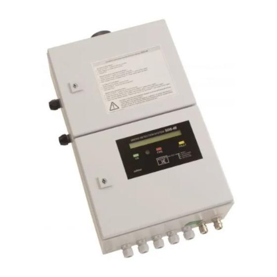
Smoke Detection System
DOK02.051
SDS-48
For Cargo Holds Onboard Ships
acc. to FSS Code Chapter 10
SMOK E D E TEC TIO N SY ST EM
ON
safetec
Operation Manual
Smoke Detection System SDS-48
S DS
FIR E
F AU LT
AC C EP T
T E S T
RE S E T
T OGGL E F A NS
D IA GNOS E S
ON- / OF F L I N E
02.04.2008
Issue 3.21
Advertisement
Table of Contents

Related Manuals for Safetec SDS-48

Summary of Contents for Safetec SDS-48
- Page 1 Smoke Detection System SDS-48 Smoke Detection System SDS-48 For Cargo Holds Onboard Ships acc. to FSS Code Chapter 10 S DS SMOK E D E TEC TIO N SY ST EM FIR E F AU LT AC C EP T...
- Page 2 Smoke Detection System SDS-48 safetec Brandes und Niehoff GmbH Arenskule 7-9 D-21339 Lüneburg Germany Tel.: ++49 - 4131 – 7670-200 Fax.: ++49 - 4131 – 7670-201 E-Mail: mail@safetec-online.com Internet: www.safetec-online.com Smoke Detection System Approvals for SDS-48: American Bureau of Shipping...
-
Page 3: Table Of Contents
Smoke Detection System SDS-48 page 26 (article no. fuse) and drawing SDS02.301 (Rev. 4), inserted prefilter data sheet and current details on fan unit drawing 3.21 02.04.2008 Changed Cable Type MGH to MPRX; Changed current for ext. Sounder to 0,7A on Drawings SDS02.081 - SDS02.095... - Page 4 Smoke Detection System SDS-48 5.2.7 Contrast of Display........................25 5.3 R ..................26 EPAIRING AND EPLACING EFECTIVE ARTS 5.3.1 Replacing a Pressure Switch ......................26 5.3.2 Replacing a Smoke Detector......................26 5.3.3 Cleaning a Smoke Detector ......................26 5.3.4 Replacing the Power Supply Module.....................27 5.3.5 Replacing the Control Module in the Smoke Detection Panel............27...
-
Page 5: Overview
Smoke Detection System SDS-48 1 Overview The smoke detection system SDS-48 is used for continual smoke monitoring in up to 48 cargo holds. For this a network of pipes simultaneously draws air samples from all cargo spaces, which are then fed to the smoke detection panel. -
Page 6: Technical Description
Smoke Detection System SDS-48 2 Technical Description 2.1 System Description A typical smoke detection system consists of the following primary components: • a smoke detection panel with or without integrated connections for detection lines • one or more repeater panels on the bridge or in the fire control room for remote display of alarms and fault warnings •... -
Page 7: Extension Panel
Smoke Detection System SDS-48 In addition to the components in the smoke detection panel SDS-0, the smoke detection panels SDS-4 and SDS-8 contain integrated detector boxes, located in an additional housing. Both housings are permanently attached to each other. -
Page 8: Repeater Panel
Smoke Detection System SDS-48 2.2.3 Repeater Panel The repeater panel allows for optical and audible alarm for all fire alarms and fault warnings, parallel to the smoke detection panel, and for the operation of the smoke detection system. It can be installed at any place on the ship and is available in wall-mounted form or for installation in a console. -
Page 9: Relay Module And Relay Box
Smoke Detection System SDS-48 2.2.5 Relay Module and Relay Box If needed, the optional relay module makes voltage-free fire alarm contacts available for every detection line. For smoke detection systems with up to 8 detection lines, the relay module can be integrated into the smoke detection panel. -
Page 10: Safeguarding Against Explosion
Smoke Detection System SDS-48 2.5 Safeguarding Against Explosion The areas in the smoke detection panel, in the extension panel(s) and in the fan units where air drawn from the monitored holds passes through are designed to safeguard against explosion. The areas of the smoke detection panel and extension panel(s) where air passes through are designed “intrinsically safe”... -
Page 11: Installation And Initial Start-Up
Smoke Detection System SDS-48 3 Installation and Initial Start-up 3.1 Installation Location The smoke detection panels and any extension panels are generally installed in the CO2 room. However they can also be affixed on the bridge. When installing the smoke detection system outside of the bridge, a repeater panel, available either for mounting on a wall or in a console, will be installed on the bridge to report fire alarms and fault warnings. - Page 12 For proper airflow it will be vital to determine the correct air pipe size. Total number of detection lines and length of air pipe must be considered by planning staff. Safetec to be informed about total number of detection lines, for evaluation of correct hose sockets.
-
Page 13: Cable Types
Smoke Detection System SDS-48 3.3 Cable Types Connection Cable type *) Remarks main power supply MPRX 3G 1.5 emergency power supply MPRX 3G 1.5 fan 1 MPRX 3G 1.5 fan 2 MPRX 3G 1.5 extension panel(s) FMGCH 1 x 2 x 0.75... -
Page 14: Voltage-Free Relay Contacts
Smoke Detection System SDS-48 3.5 Voltage-free Relay Contacts Voltage-free relay contacts are available for the following signals (switch over contacts, max. load: 42V~/60V=/1.25A): • Fault warning: The relay for fault warning is activated when the smoke detection system has no fault warnings (normal operation). -
Page 15: Fuses
Smoke Detection System SDS-48 3.7 Fuses Fuses on the Power Supply Module All fuses comply with IEC 127 - 6 or EN 60127 - 6, size 5 x 20 mm. Fuse Description Type Transformer fuse 250 mA slow blowing Note: By removing this fuse the smoke detection system can be removed from operation. -
Page 16: Initial Start-Up And Service Checklist
Smoke Detection System SDS-48 3.8.2 Initial Start-up and Service Checklist Steps o.k. o.k. Smoke Collectors Check for location and secure mounting of the smoke collectors in the monitored areas. Pipe and Hose Connections Check all pipe and hose connections for secure fastening and support. - Page 17 Smoke Detection System SDS-48 13 Power Supply Check function of main and emergency power monitoring. For this, switch off the main and the emergency power supply one at a time. A corresponding fault warning “FAULT: Main Supply” or “FAULT: Emergency Supply” must appear.
-
Page 18: Operation
4.2 Start-up Notification After starting or resetting the smoke detection system, the following message will appear: ====== Smoke Detection System SDS-48 ======= V 1.0 The system designation and the version number of the software will be displayed. After a short... -
Page 19: Normal Operation
Smoke Detection System SDS-48 4.3 Normal operation Under normal operation • the green lamp is on (= running) and • the LCD displays “NORMAL OPERATION” • the active fan is indicated NORMAL OPERATION ACTIVE: Fan -1- 4.4 Fire Alarm If smoke is detected in the air sample of a detection line, •... -
Page 20: Fault Warnings
Smoke Detection System SDS-48 4.5 Fault Warnings If the smoke detection panel detects a fault, • the buzzer sounds with a intermittent signal • the yellow lamp (= fault) flashes and • the LCD gives information on the fault, i.e.:... -
Page 21: Reset Function (Proceed Reset)
Smoke Detection System SDS-48 Proceed Reset ? If yes, press button again ! Switch over or stop Fans ? If yes, press button again ! Display Diagnoses of Smoke Detectors ? If yes, press button again ! Select On- / Offline ? If yes, press button again ! Each of the special functions can be selected by pressing the button while it is shown on the LCD. -
Page 22: Display Smoke Detector Diagnosis Report (Display Diagnoses
Smoke Detection System SDS-48 4.8.4 Display Smoke Detector Diagnosis Report (Display Diagnoses ...) The smoke detectors automatically self-correct their alarm threshold as they become dirty in order to have a uniform response sensitivity. If they become too dirty, a corresponding fault warning will occur. -
Page 23: Maintenance And Correcting Faults
Smoke Detection System SDS-48 5 Maintenance and Correcting Faults 5.1 Functioning Test 5.1.1 Daily Routine Tests • Operation: Check whether the green lamp at the repeater panel or at the smoke detection panel is on • Fault Indications: Check the smoke detection panel or the repeater panel for any fault warnings. -
Page 24: Display Of Fault Warnings
Smoke Detection System SDS-48 5.2 Display of Fault Warnings Nearly all possible system faults of the smoke detection system SDS-48 will be indicated on the display. Please find hereafter a description of all possible fault indications. 5.2.1 Airflow Fault... -
Page 25: Defective Smoke Detector
Smoke Detection System SDS-48 5.2.3 Defective Smoke Detector If the smoke detection panel cannot get in contact with the smoke detector in detection line no. x, the following fault warning will be issued: FAULT: Smoke Detector Line -x- Possible causes: •... -
Page 26: Power Supply Failure
Smoke Detection System SDS-48 5.2.5 Power Supply Failure If the main power supply fails, the following fault warning will be issued: FAULT: Main Supply If the emergency power supply fails, the following fault warning will be issued: FAULT: Emergency Supply 5.2.6 Failure of Fan Unit... -
Page 27: Repairing And Replacing Defective Parts
Smoke Detection System SDS-48 5.3 Repairing and Replacing Defective Parts 5.3.1 Replacing a Pressure Switch 1. Open the lower door of the smoke detection panel and turn the smoke detection system off. (Remove transformer fuse F1 on power supply module). -
Page 28: Replacing The Power Supply Module
Smoke Detection System SDS-48 5.3.4 Replacing the Power Supply Module 1. Turn off main and emergency power. 2. Open the smoke detection panel. 3. Remove the cable connections. 4. Remove the fastening screws for the power supply module (7 screws). -
Page 29: Replacing The Fan Unit Sds-M0440
Smoke Detection System SDS-48 5.3.8 Replacing the Fan Unit SDS-M0440 1. Turn off the main and emergency power supply for the smoke detection system at the main and emergency switchboards for the ship. 2. Undo the connecting cable in the terminal block at the motor. -
Page 30: Spare Parts
Smoke Detection System SDS-48 5.4 Spare Parts Standard Art. No. Name Type Spare Part Packet BG02.001 BG02.03x Pipe connecting parts at SDS-devices BG02.300 Adapter for repeater panel SDS-R48 BG02.500 Control module for smoke detection panel BG02.510 Control module for repeater panel BG02.600... -
Page 31: Configuration Of The Smoke Detection System
Smoke Detection System SDS-48 6 Configuration of the Smoke Detection System IMPORTANT NOTE: Configuration of the SDS smoke detection system is already carried out by manufacturer, prior to delivery. Observe to the following instruction only, if a spare part is to be configured... -
Page 32: Setting The Highest Line And Address Number
Smoke Detection System SDS-48 6.2 Setting the Highest Line and Address Number For the purpose of self supervision the smoke detection panel must know the highest detection line number and the highest address number of the actual system. These values will be determined and saved in a semi-automatic configuration mode. - Page 33 “1”. The smoke operating mode detection system will now begin with its normal operation. After the start message “Smoke Detection System SDS-48” a message similar to the following will appear for about 6 seconds: System Configuration: Lines: 8 Address: 1 of 2 After that, the smoke detection system will automatically be in normal monitoring operation.
-
Page 34: Customer-Specific Adaptations For Fire Alarm Display
For this, safetec offers two different solutions that will be explained in the following section. - Page 35 Smoke Detection System SDS-48 Instructions for Configuring the Fire Alarm Using the “ACCEPT” button The configuration is performed with the help of the dialogue on the display and with the ACCEPT button. During the configuration, different questions will be put to you.
- Page 36 Smoke Detection System SDS-48 Step Action Instructions Press the ACCEPT button until the following read-out Calling up “special appears on the display: functions” Select special functions ? If yes, press button again ! Call up special functions by pressing the button again.
- Page 37 Smoke Detection System SDS-48 Wait until the next acoustic signal. The display will Selecting the display then show i.e.: mode for reporting a fire Actual adjustm: Displ. w/out cargo hold-no Toggle display mode ? If you want to change the display mode, press the ACCEPT button.
- Page 38 Smoke Detection System SDS-48 Wait until the next acoustic signal. The display will Changing the access then show: code Change access code ? If yes, press button again ! If you don’t wish to change the access code, you only need to wait until the normal operating program is started and skip to step 8.
- Page 39 For proper airflow it will be vital to determine the correct air pipe size. Total number of detection lines and length of air pipe must be considered by planning staff. Safetec to be informed about total number of detection lines, for evaluation of correct hose sockets.
- Page 40 Material: polyurethane soft foam / stainless steel wire Material : Polyurethan-Weichschaumstoff / Niro-Draht Arenskule 7- 9 D - 21339 Lüneburg Tel.: 04131 – 7670 200 Fax.: 04131 – 7670 201 mail@safetec-online.com E-Mail: Internet: www.safetec-online.com REV. 0 / 03.02.03 / JaPe...
- Page 41 Rauchmeldezentrale eingebaut werden. Relaiskontakte / Description Relay Contacts The Smoke Detection Panel of the SDS-48-system 42V~ / 60= / 0,5A has as a standard one fire alarm relay, which will be activated during fire alarm on any detection line. If a...
- Page 42 Pos. 5-7 Größe abhängig von der to Cargo Holds Anzahl der Meldelinien size depends on total number of detection lines (siehe Zeichnung BG02.03x / see drawing BG02.03x) Beispiel: Rauchmeldeanlage SDS-48 mit 12 Kanälen Rev. 18.07.07 Maßstab safetec 18.07.07 SDS02.010.12.tcd Gepr.
- Page 43 If a optional relay module will be mounted, this will be placed right from the power supply module. Gepr. 15.08.07 The galvanic isolator will then be mounted left from the power supply module (positions are shown dotted). 26.04.00 Bearb. Teile in Rauchmeldezentrale SDS-4 SDS02.021.tcd safetec Components in Smoke Detection Panel SDS-4...
- Page 44 13 Kanäle 14 Kanäle 12 Lines 13 Lines 14 Lines 15 Kanäle 16 Kanäle 17 Kanäle 15 Lines 16 Lines 17 Lines Maßstab Rev. 20.06.00 Gepr. 1:30 Bearb. 20.04.00 Standardausführung der Rauchmeldesys. SDS-48 safetec SDS02.031.tcd Standard Supply of Smoke Detection Panels...
- Page 45 25 Kanäle 24 Lines 25 Lines 26 Kanäle 27 Kanäle 26 Lines 27 Lines 28 Kanäle 29 Kanäle 28 Lines 29 Lines Maßstab Rev. 20.06.00 Gepr. 1:30 Bearb. 20.04.00 Standardausführung der Rauchmeldesys. SDS-48 safetec SDS02.032.tcd Standard Supply of Smoke Detection Panels...
- Page 46 Art. Nr. Z01.004 Maßstab Maßstab Scale Scale PVC-Reduzierung für DN50 und DN40 Rohre PVC- Reduction for DN50 and DN40 pipes Art.Nr. Z04.016 63,0 50,0 75,0 90,0 Rev. 16.08.07 Maßstab Gepr. 16.08.07 02.05.00 Bearb. Rohr- und Schlauchverbindungen safetec SDS02.061.tcd Hose and Pipe Fittings...
- Page 47 SMOKE DETECT I ON SYST EM SMOKE DETECT I ON SYST EM 120 Ω 120 Ω FIRE FAULT FIRE FAULT ACCEPT ACCEPT safetec safetec Rauchmeldezentrale Fernanzeigerät 1 Fernanzeigerät 2 Relaisbox Smoke Detection Panel Repeater Panel 1 Repeater Panel 2 Variante 2: 120 Ω...
- Page 48 The fault relay is shown in deactivated state under fault condition. and 2 are required Anschlussplan Rauchmeldezentrale SDS-0 mit 1 Erweiterungsgerät Rev. 02.04.08 JaPe Maßstab safetec 02.04.08 SDS02.081.tcd Gepr. Terminal Plan Smoke Detection Panel SDS-0 with 1 Extension Panel Bearb. 26.10.00...
- Page 49 The fault relay is activated, when no fault is detected. The fault relay is shown in deactivated state under fault condition. Anschlussplan Rauchmeldezentrale SDS-4/SDS-8 ohne Erweiterung Rev. 02.04.08 JaPe Maßstab safetec SDS02.085.tcd 02.04.08 Gepr. Terminal Plan Smoke Detection Panel SDS-4/SDS-8 without Ext. Bearb. 26.10.00...
- Page 50 The fault relay is activated, when no fault is detected. The fault relay is shown in deactivated state under fault condition. Rauchmeldezentrale SDS-4/SDS-8 + 1 Erweiterungsgerät SDS-E8 Rev. 02.04.08 JaPe Maßstab safetec SDS02.086.tcd 02.04.08 Gepr. Smoke Detection Panel SDS-4/SDS-8 + 1 Extension Panel SDS-E8 Bearb. 26.10.00...
- Page 51 The fault relay is activated, when no fault is detected. The fault relay is shown in deactivated state under fault condition. Rev. 02.04.08 JaPe Maßstab Rauchmeldezentrale SDS-4/SDS-8 + Erweiterungsgerät SDS-E12/SDS-E16/SDS-EC16 safetec SDS02.087.tcd 02.04.08 Gepr. Smoke Detection Panel SDS-4/SDS-8 + Extension Panel SDS-E12/SDS-E16/SDS-EC16 Bearb. 26.06.01...
- Page 52 The fault relay is activated, when no fault is detected. The fault relay is shown in deactivated state under fault condition. Rev. 02.04.08 JaPe Maßstab Rauchmeldezentrale SDS-4/SDS-8 + Relaismodul + Fernanzeigegerät safetec SDS02.089.tcd 02.04.08 Gepr. Smoke Detection Panel SDS-4/SDS-8 + Relay Module + Repeater Panel Bearb. 15.05.01...
- Page 53 The fault relay is activated, when no fault is detected. The fault relay is shown in deactivated state under fault condition. Rev. 02.04.08 JaPe Maßstab Anschlussplan Rauchmeldezentrale SDS-4/SDS-8 mit 2 Fernanzeigegeräten safetec SDS02.095.tcd 02.04.08 Gepr. Terminal Plan Smoke Detection Panel SDS-4/SDS-8 with 2 Repeater Panels Bearb. 30.01.01...
- Page 54 SMOKE DETECTION SYSTEM FIRE FAULT TEST RESET ACCEPT TOGGLE FANS DIAGNOSES safetec ON- / OFFLINE 4 x D=11 Technische Daten Technical Data Maße (HxBxT, nur Gehäuse): 300 x 380 x 210 mm Size (HxBxD, enclosure only) Gewicht: 12 kg Weight Betriebstemperatur: 0°C - 55°C...
- Page 55 SMOKE DETECTION SYSTEM FIRE FAULT ACCEPT TEST RESET TOGGLE FANS DIAGNOSES safetec ON- / OFFLINE 4 x D=11 Technische Daten Technical Data Maße (HxBxT, nur Gehäuse): 600 x 380 x 210 mm Size (HxBxD, enclosure only) Gewicht: 25 kg (4Linien / 4 Lines)
- Page 56 SMOKE DETECTION SYSTEM FIRE FAULT ACCEPT TEST RESET TOGGLE FANS DIAGNOSES safetec ON- / OFFLINE 4 x D=11 Technische Daten Technical Data Maße (HxBxT, nur Gehäuse): 900 x 380 x 210 mm Size (HxBxD, enclosure only) Gewicht: 40 kg (8 Linien / 8 Lines)
- Page 57 SMOKE DETECTION SYSTEM FIRE FAULT ACCEPT TEST RESET TOGGLE FANS DIAGNOSES safetec ON- / OFFLINE 4 x D=11 Technische Daten Technical Data Maße (HxBxT, nur Gehäuse): 1200 x 380 x 210 mm Size (HxBxD, enclosure only) Gewicht: 55 kg (12 Linien / 12 Lines)
- Page 58 Article Nos. 5 Linien / Lines SDS02.205 6 Linien / Lines SDS02.206 7 Linien / Lines SDS02.207 8 Linien / Lines SDS02.208 Rev. 15.08.07 Maßstab Gepr. 15.08.07 1:10 Bearb. 26.04.00 Datenblatt Erweiterungsgerät SDS-E8 safetec SDS02.208.01.tcd Data Sheet Extension Panel SDS-E8...
- Page 59 Article Nos. 9 Linien / Lines SDS02.209 10 Linien / Lines SDS02.210 11 Linien / Lines SDS02.211 12 Linien / Lines SDS02.212 Rev. 15.08.07 Maßstab Gepr. 15.08.07 1:10 Bearb. 26.04.00 Datenblatt Erweiterungsgerät SDS-E12 safetec SDS02.212.01.tcd Data Sheet Extension Panel SDS-E12...
- Page 60 Article Nos. 13 Linien / Lines SDS02.213 14 Linien / Lines SDS02.214 15 Linien / Lines SDS02.215 16 Linien / Lines SDS02.216 Rev. 15.08.07 Maßstab Gepr. 15.08.07 1:10 Bearb. 26.04.00 Datenblatt Erweiterungsgerät SDS-E16 safetec SDS02.216.01.tcd Data Sheet Extension Panel SDS-E16...
- Page 61 12 Linien / Lines SDS02.232 13 Linien / Lines SDS02.233 14 Linien / Lines SDS02.234 15 Linien / Lines SDS02.235 16 Linien / Lines SDS02.236 Rev. 20.12.05 Maßstab Gepr. 20.12.05 1:10 25.04.03 Bearb. Datenblatt Erweiterungsgerät SDS-EC16 safetec SDS02.236.01.tcd Data Sheet Extension Panel SDS-EC16...
- Page 62 SMOKE DETECTION SYSTEM FIRE FAULT ACCEPT TEST RESET SWITCH FANS DIAGNOSES safetec ON- / OFFLINE Deckel / Cover Unterteil / Base 4 x Ø 7mm Befestigungspunkte, Ansicht von hinten Fixing points, view from behind Technische Daten Technical Data Maße (HxBxT, nur Gehäuse):...
- Page 63 SMOKE DETECTION SYSTEM FIRE FAULT ACCEPT TEST RESET TOGGLE FANS DIAGNOSES safetec ON- / OFFLINE Pult / Desk Panel Frontplatte / Cover Plate M6x70 Schutzgehäuse / Enclosure Federring / Lock Washer Mutter / Nut M6 Befestigungsschrauben für Frontplatte nicht dargestellt...
- Page 64 Raum: 300mm über und 50mm seitlich neben Lüfteraggregat Method of Installation: upright on shock mounts clearance: 300mm above and 50mm beside fan unit Rev. 15.08.07 Maßstab Artikelnummer SDS02.440 Gepr. 15.08.07 1:10 Article No. 25.06.00 Bearb. Datenblatt Lüfteraggregat SDS-M0440 safetec SDS02.440.01.tcd Data Sheet Fan Unit SDS-M0440...
- Page 65 Raum: 300mm über und 50mm seitlich neben Lüfteraggregat Method of Installation: upright on shock mounts clearance: 300mm above and 50mm beside fan unit Artikelnummer SDS02.441 Article No. Rev. 15.08.07 Maßstab Gepr. 15.08.07 1:10 30.07.01 Bearb. Datenblatt Lüfteraggregat SDS-M0441 safetec SDS02.441.01.tcd Data Sheet Fan Unit SDS-M0441...
- Page 66 Bemerkung: 1. Der Leistungsschalter ist auf der Lüftereinheit montiert 2. Die gestrichelten Linien sind bereits von safetec verdrahtet 3. Die Drehrichtung des Motors ist im Uhrzeigersinn 4. Die Zeichnung für Lüfter Nr.2 ist identisch 5. Leistungsschalter auf 6A einstellen.
Need help?
Do you have a question about the SDS-48 and is the answer not in the manual?
Questions and answers
Are spare parts rep and or service dealers in USA.