
Related Manuals for Mostec M4020


Summary of Contents for Mostec M4020
- Page 1 Operating Instructions pH/ORP Controller Type M4020 / M4020R M4020OM V1.11e/13.06.2024...
-
Page 2: Revision
Revision Version Date Changes V1.00 02.03.2023 Valid for M4020/M4020R as of firmware version 1.00.12 First edition. V1.10 04.04.2023 Valid for M4020/M4020R as of firmware version 1.00.16 Behavior of current output in case of alarm. Hold mode of current output and limit values V1.11... -
Page 3: Table Of Contents
Operating instruction manual M4020 Chapter: Content Content Revision ....................................2 Content ..................................... 3 Operating notes ..................................4 Warranty ...................................... 4 Technical description ................................... 4 Technical support ..................................4 Contact details ..................................4 Safety instructions ..................................5 Operating regulations .................................. 5 Wiring diagram .................................... -
Page 4: Operating Notes
The warranty repair must in any case be carried out at Mostec. Postage and packaging expenses shall be paid by the customer. In the event of a warranty claim, the repaired unit will be returned at Mostec's expense. Transport damages are excluded from any warranty service and must be reported to the delivering carrier. -
Page 5: Safety Instructions
Operating instruction manual M4020 Chapter: Operating notes Safety instructions Observe the customary national regulations and safety requirements for electrical, light and heavy current installations. Read and observe the safety regulations of this operating manual before using the device. The device must be mounted in such a way that it is protected from moisture, vibrations and heavy soiling. -
Page 6: Wiring Diagram
Operating instruction manual M4020 Chapter: Operating notes Wiring diagram Typical connection Page 6... -
Page 7: Connections
Operating instruction manual M4020 Chapter: Operating notes Connections 4-20mA input active Loop powered supply GND for 4-20mA active signal / Loop powered Hold input +24V/25mA signal sensor Pt-100 probe (+) GND for hold input Pt-100 probe (-) Pt-100 sensor sense(-) -
Page 8: Instrument Overview
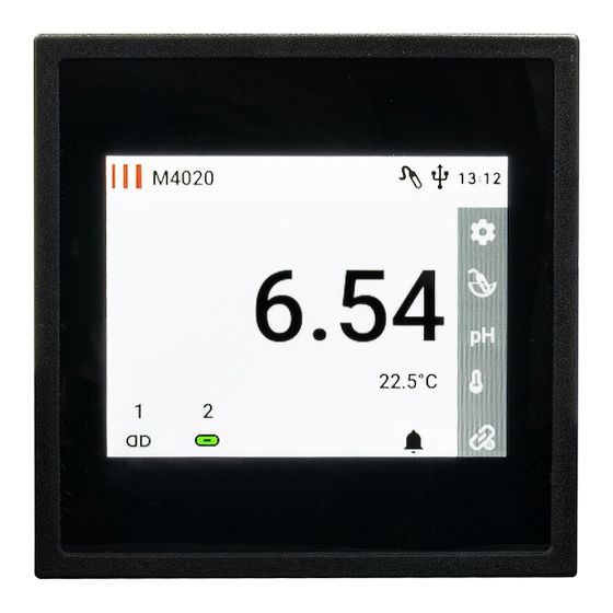
Operating instruction manual M4020 Chapter: Instrument overview Instrument overview Instrument elements Measurement screen 1. Current measured values 2. Logo and "Device info" entry 3. Device label 4. Status bar with current time 5. Settings 6. Calibrate pH probe 7. Measured variable 8. -
Page 9: User Menu
The bar on the right side is a scroll bar The M4020 comes in two versions: Version pH final check (M4020GW) and version pH-controller (M4020R). Specific settings for the M4020R are described in the chapter “OOperation of the M4020R version. See Seite 19... -
Page 10: Measurement Settings
Operating instruction manual M4020 Chapter: User menu Measurement settings In this submenu, measurement-specific settings as well as settings for the current output can be made. Menu item Function/Comment Possible values Current output 1 Settings for signal output 1 Signal output 1 & 2 settings... -
Page 11: Signal Output 1 & 2 Settings
Operating instruction manual M4020 Chapter: User menu Signal output 1 & 2 settings Menu item Function/Comment Possible values Input min Minimum pH / mV / temperature value Adjustable from: for the lower value of the current -1000mV to +1000mV output -2.00pH to +16.00pH... -
Page 12: Device Settings
Operating instruction manual M4020 Chapter: User menu Device settings Device specific settings are made in this submenu. Menu item Function/Comment Possible values Language Setting the menu language English German Français Access code Activate/deactivate the access code. Numeric access code When the access code is active, only Size: 4 digits the menu items "Sensor calibration"... -
Page 13: Limit 1 & 2 Settings
Operating instruction manual M4020 Chapter: User menu Limit 1 & 2 settings Menu item Function/Comment Possible values Set point Set the setpoint value of the limit Adjustable from: contact -1000mV to +1000mV -2.00pH to +16.00pH -30.0°C to +130.0°C GW1: [8.00pH / +150mV / 45.0°C] GW2: [6.00pH / -150mV / 25.0°C]... -
Page 14: Alarm Settings
Operating instruction manual M4020 Chapter: User menu Alarm settings Menu item Function/Comment Possible values Alarm SP1 Opens the Alarm SP1 settings See Alarm SP1 & SP2 settings Alarm SP2 Opens the Alarm SP2 settings See Alarm SP1 & SP2 settings... -
Page 15: Usb Settings
Operating instruction manual M4020 Chapter: User menu USB settings Menu item Function/Comment Possible values Log interval Time interval between measurements Adjustable from: will be stored on the USB stick 1s to 7200s [5s] Time Set the current time Adjustable from: 00:00 to 23:59 Shows the status. -
Page 16: Operation Of The Instrument
Operating instruction manual M4020 Chapter: Operation of the instrument Operation of the instrument Calibration of the pH- probe This chapter describes how to calibrate a pH probe. The calibration screen can be activated by pressing the icon on the measurement screen or from the “Measurement settings” submenu. -
Page 17: Alarm Log
Operating instruction manual M4020 Chapter: Operation of the instrument Alarm Log 1. Alarm Log Symbols 2. Current alarm state 3. Alarm state history 4. Alarm acknowledgement Explanation of the Alarm Log Symbols Alarm contact active Limits points have triggered an alarm... -
Page 18: Usb Logger
Operating instruction manual M4020 Chapter: Operation of the instrument USB Logger Features of the USB Logger The device only accepts USB sticks which are FAT32 formatted and empty. Time and date must be set before inserting the USB stick. These settings are retained in the de-energized state via a backup battery. -
Page 19: Operation Of The M4020R Version
Operating instruction manual M4020 Chapter: Operation of the M4020R version Operation of the M4020R version The device can be operated either as a final check version (M4020GW) or as a controller type (M4020R). In this chapter, the setting options and the operating modes of the controller will be explained. -
Page 20: Explanation Of The Control Operations
Operating instruction manual M4020 Chapter: Operation of the M4020R version Explanation of the control operations With two different set points In control mode, a dead band is created between set point 1 (W1) and set point 2 (W2) in which the controller is not active. -
Page 21: Fitting The Controller To A Titration Curve
Operating instruction manual M4020 Chapter: Operation of the M4020R version Fitting the controller to a titration curve If fast-acting electro valves are used for a process, it is naturally advantageous to keep the valve switching times or the time ratios Xt on and Xt off as small as possible. If hydraulic or pneumatic valves are required, the times must be increased accordingly due to the relatively long opening and closing times of these valves. -
Page 22: Appendix
Operating instruction manual M4020 Chapter: Appendix Appendix Dimensions Front panel mounting requires a cutout of 91x91mm. Side view: Rear view: Page 22... -
Page 23: Technical Data
Operating instruction manual M4020 Chapter: Appendix Technical data Measuring ranges: -2.00 to 16.00pH -1000 to +1000mV Display resolution: 0.01pH Accuracy @25°C: 0.01pH Long-term stability: 0.02pH 3mV (per year at 23°C) Display: Sunlight readable 3.5'' IPS graphic display, 320x240 pixels Working temperature range: -5°C to +45°C... - Page 24 Operating instruction manual M4020 Chapter: Appendix Power supply: Universal power supply: 20 to 253VAC or DC Power consumption: 4.0W to 7.0W at 230VAC CE conformity: fullfilled Connection type: Connector terminals: 2x 3 pin, 1x 6 pin, 1x 8 pin, 1x 9 pin, 1x 8pin...
Need help?
Do you have a question about the M4020 and is the answer not in the manual?
Questions and answers