
Related Manuals for STRECKEISEN SEISMIC INSTRUMENTATION STS-2

Summary of Contents for STRECKEISEN SEISMIC INSTRUMENTATION STS-2
- Page 1 STRECKEISEN EISMIC NSTRUMENTATION ELOCITY ROADBAND EISMOMETER STS-2.5 NSTRUCTION ANUAL Revision 1.1 – Dec 10, 2013...
-
Page 3: Important Notices - Please Read, Before Working With The Equipment
Do not connect the host box type 3-320.02 or the cable type 3-384.xx that comes with this sensor package to an STS-2. „ Do not connect an STS-2 cable or its host box to an STS-2.5 sensor. There will be no damage to the equipment but it will not work. „... -
Page 4: Table Of Contents
4.3. Setting up the sensor Operation - Getting started 5.1. Host box Users Interface 5.2. Hostbox electrical interface (connection to the digitizer) 5.3. Interface differences of STS-2 and STS-2.5 Calibration 6.1. Accuracy Limitations of the on-site calibration 6.2. Electrical calibration interface 6.3. -
Page 5: Introduction
EISMIC NSTRUMENTATION Introduction The STS-2.5 is a high performance VBB seismometer designed for quick and simple installation, wide temperature range operation, and secure transport, while resolving minimum earth noise levels over most of the seismometer’s pass band. Like the predecessors STS-1 and STS-2, the STS-2.5 is an electronic force-feedback sensor that provides an output signal proportional to ground velocity over a broad range. -
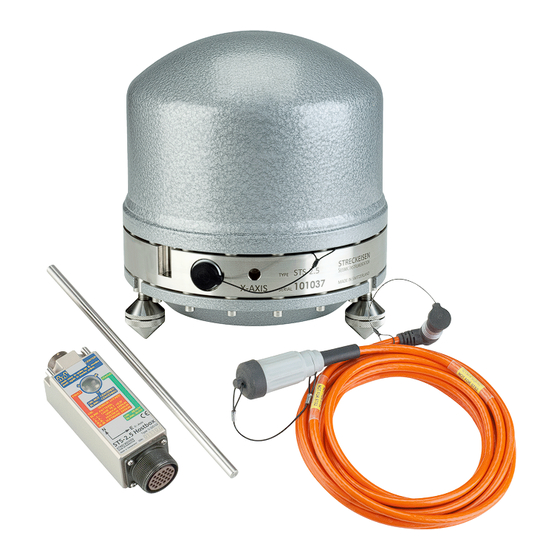
Page 6: Unpacking The Sensor And Contents Of The Package
Avoid wet location. Although the equipment is watertight regular and/or longer immersion in probably aggressive water will cause corrosion over the years. If possible attach the host box to a wall or put it on an elevated place. STS-2.5 I V1.1 © Streckeisen GmbH, Switzerland. All rights reserved. NSTRUCTION... - Page 7 A disadvantage is its ability to convect. Even the convection that establishes due to its own power dissipation may suffice for the STS-2.5 to produce a horizontal noise that is five times higher than the quiet-conditions vertical one. Experience has shown that the convection-driven horizontal noise increases with the freely circulating air volume under the shielding.
-
Page 8: Prepare The Sensor
(i.e fund with obsolete military structures) The STS-2.5 sensor can be deployed in a hole, provided that the feet screws are accessible in order to level the seismometer. In a hole, apart from the elevated temperature stability, a small-area superficial tilt signal stemming from human activity or atmospheric processes is damped down as a quadratic function of burial depth. - Page 9 Bubble level Finally tighten all three feet by turning their counter nuts clockwise until they lock firmly. Check it. A loose foot will strongly compromise the signal quality. STS-2.5 I V1.1 © Streckeisen GmbH, Switzerland. All rights reserved. NSTRUCTION ANUAL...
-
Page 10: Operation - Getting Started
RED status LED is steadily on. Power down and pack. Do not forget to cover the sensor connector with its protection cap. Remote control from a Q330 is performed the same way as for an STS-2, except that a wake-up command by activating either control input (Pin E, K, L) must precede the operational command whenever the HB is asleep (typically after a period of inactivity). -
Page 11: Host Box Users Interface
† Connector digitizer side 24pol neg. Mating connector: CA3106PG24-28P-A176 mating cable: KMI 110959 ‡ Connector sensor side Mating cable: the provided sensor cable type 3-348.xx STS-2.5 I V1.1 © Streckeisen GmbH, Switzerland. All rights reserved. NSTRUCTION ANUAL... -
Page 12: Hostbox Electrical Interface (Connection To The Digitizer)
Sensor case and sensor cable shield 5.3. Interface differences of STS-2 and STS-2.5 The table below shows the pins with different functions and what happened when an STS-2.5 is directly replaced with an STS-2 by attaching it to the existing 24-pin digitizer cable. -
Page 13: Calibration
2 the parameter stability has proven excellent (long-term drift <±0.3 % in ten years), and the one of STS-2.5 will not be worse, because it uses the same components and materials for the crucial parts. Therefore, absolute calibration has not to be repeated for the whole lifetime, provided that the instrument is handled carefully according to the advices given in this manual. -
Page 14: Electrical Calibration Interface
Output Signal polarity as a function of motion Provided that the STS-2.5 is properly oriented, the signal output polarities + to - (differential) and POS/RAW/CAL to signal ground (GNDS, single-ended) are as follows. Seismic signal outputs... -
Page 15: Technical Background
STS-2.5. 8.1. General description Apart from the control functions, the principle of operation of STS-2.5 is identical to the one of STS-2. Users will find the terms they used when dealing with STS-2 still valid for STS-2.5. Additionally, the feedback elements of STS-2.5 guarantee virtually the same response to ground motion as for the... -
Page 16: Block Diagram
: Radius of inertia [ where J = inertia relative to the pendulum rotation axis] m: Pendulum mass ω : Pendulum cycle frequency and damping constant of the mechanical free oscillation STS-2.5 I V1.1 © Streckeisen GmbH, Switzerland. All rights reserved. NSTRUCTION ANUAL... -
Page 17: Short-Period Or Fast-Response Mode
Moreover, the suspension used for the STS-2.5 pendulums is one of the many possible realizations of a so-called astatic suspension allowing a very high free mechanical oscillation period up to virtual infinity. The higher the period the lower is its contribution to the long-period noise. -
Page 18: Ambient Temperature Limits
“Table of parameters” below are approximate mean values evaluated using a set size of about 300 STS-2.5 test results. The model part is introduced, in order to account for the slightly different response that exists between excitation by ground motion and excitation by forced feedback coil current. -
Page 19: Theoretical Transformation Equations UvwåÆXyz
“exact” parameters is not needed for sensor component-related glitch and defect localization, i.e. the formulas given above suffice for these purposes. Noise Performance This section is currently being reevaluated. STS-2.5 I V1.1 © Streckeisen GmbH, Switzerland. All rights reserved. NSTRUCTION ANUAL... -
Page 20: Long-Period Vertical Vs. Long-Period Horizontal Noise
This statement is also valid for a 3-component seismometer, like the STS-2.5, which builds horizontal and vertical components by axis transformation. -
Page 21: Maintenance
Sensor and host box do not contain any maintainable parts inside. Opening of either sensor or host box can cause malfunction and void warranty. After returning from field installation the STS-2.5 should be treated with a mild agent rather than with aggressive chemicals. Be sure the protection cap sticks firmly in the sensor connector. -
Page 22: Troubleshooting Hints
(see also section 8.5 Ambient temperature limits). Note: A broad-band signal looks rather different from a short-period one. For the STS-2.5, any long- period (>120s) change of the internal or external force on the boom deflects the signal proportional to the derivative of this force. -
Page 23: Deployment Related Spurious Signal Phenomena
Please contact Streckeisen GmbH in case of uncertainty. 10.3. Return to repair If an STS-2.5 needs to be repaired, please contact Streckeisen in advance in any case. We can provide helpful information. Please send, if possible, instrument, cable and hostbox to the address at the end of this manual. -
Page 24: Frequently Asked Questions (Faqs)
Z together with the calculated X and Y differences. As a further benefit, the reference Z can be used as an independent discrimination agent: A glitch that is found on both Z curves, independent of the amplitude ratio, must be of external origin. STS-2.5 I V1.1 © Streckeisen GmbH, Switzerland. All rights reserved. NSTRUCTION... - Page 25 X and Y tilt values instead of the bubble level. Please contact Streckeisen GmbH for advices concerning the access to the serial interface. STS-2.5 I V1.1 © Streckeisen GmbH, Switzerland. All rights reserved. NSTRUCTION...
Need help?
Do you have a question about the STS-2 and is the answer not in the manual?
Questions and answers