Table of Contents

Related Manuals for TriCom TCR-NXG-50


Summary of Contents for TriCom TCR-NXG-50
- Page 1 OPERATOR’S MANUAL TCR-NXG-50 DUAL CHANNEL MULTIBAND/WIDEBAND RF AMPLIFIER DOCUMENT # 90402-00918 • Tricom Research, Inc. www.tricomresearch.com 17791 Sky Park Circle, Suite J, Irvine, CA 92614 Phone: (949) 250-6024 Fax: (949) 250-6023...
- Page 2 TCR-NXG-50 OPERATOR’S MANUAL Revision History - Document 90402-00918 REVISION DESCRIPTION DATE Initial Release 10 June 2024 Note: The latest version of this manual can be downloaded from www.tricomresearch.com.
-
Page 3: Table Of Contents
TCR-NXG-50 OPERATOR’S MANUAL TABLE OF CONTENTS INTRODUCTION General Information ..................1 Abbreviations and Glossary ................2 Equipment Description .................. 3 1.3.1 Modes and Filter Selection ................3 1.3.2 Transmit Power Levels .................. 3 1.3.3 OLED Displays ..................... 4 Amplifier Components .................. 5 Power Cable .................... - Page 4 Figure 1-3 Menu Function Display ................4 Figure 1-4 Rear Panel ....................10 Figure 3-1 TCR-NXG-50 Outline Drawing ..............19 Figure 3-2 DC Input Power Connector ............... 21 Figure 3-3 DC Power Cable ..................21 Appendix A Menu Structure ..................23...
-
Page 5: Introduction
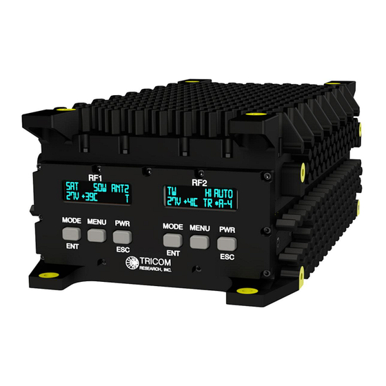
INTRODUCTION GENERAL INFORMATION The TCR-NXG-50, shown in Figure 1-1, is a true simultaneous transmit 50 Watt dual channel Multiband Next Generation RF Amplifier designed to extend the range of modern tactical communications radios. The amplifier includes support for narrowband and wideband networking waveforms. -
Page 6: Abbreviations And Glossary
ABBREVIATIONS AND GLOSSARY ANW2C Adaptive Networking Wideband Waveform Revision C APCO Association of Public Safety Communication Officials ASCM Advanced Special Communications Mode DAMA Demand Assigned Multiple Access Decibel Decibel referenced to 1 milliwatt (0 dBm = 1 mW) Direct Current Frequency Modulation Hertz Integrated Waveform... -
Page 7: Equipment Description
EQUIPMENT DESCRIPTION The TCR-NXG-50 (Tricom PN: 11000-00918) is a bi-directional half-duplex RF Power Amplifier (PA) designed to enhance communications in vehicular, airborne, maritime, man-portable, or fixed-station applications. All current military and commercial waveforms are supported including Narrowband LOS, Frequency Hopping, DAMA/IW SATCOM, Wideband Networking, and Special Communications Modes. -
Page 8: Oled Displays
35 and 50W settings are only available when the input voltage is above 22 VDC. 1.3.3 OLED DISPLAYS The TCR-NXG-50 NVG-compatible OLED displays indicate the mode of operation, power level, antenna selection, DC input power, internal temperature, and RCV/TX when in the Home Display. -
Page 9: Amplifier Components
AMPLIFIER COMPONENTS The TCR-NXG-50 Power Amplifier has a sealed, rugged enclosure finished in black anodize and designed to withstand the elements and resist corrosion. The enclosure houses all electronic subassemblies including printed circuit board assemblies, filter and switching networks, and interconnects. - Page 10 Frequency Range 225-450 MHz Frequency Range 225-450 MHz ALL TRANSMIT MODES RF Power Input 2-5W RF Power Output 12-22 VDC: 10, 15, 20W 22-32 VDC: 10, 15, 20, 35, 50W RECEIVE: VLO FM and VLO AM Frequency Range 30-118 MHz with co-site filtering Receive Gain 15 dB, 3.5 dB NF VHI FM and VHI AM...
- Page 11 Frequency Range 240-270 MHz with co-site filtering Receive Gain 15 dB, 3.5 dB NF Frequency Range 225-450 MHz Receive Gain 15 dB, 3.5 dB NF Frequency Range 225-450 MHz Receive Gain 15 dB, 3.5 dB NF BYPASS: Frequency Range 30 MHz - 1 GHz Typical Insertion Loss 1 dB Frequency Range...
- Page 12 ALL TRANSMIT MODES RF Power Input 2-5W RF Power Output 12-22 VDC: LOW/MED/HI (Power output is reduced) 22-32 VDC: LOW/MED/HI (Full output power) RECEIVE: UHF FM and UHF AM Frequency Range 225-450 MHz with co-site filtering Receive Gain 15 dB, 3.5 dB NF Frequency Range 240-270 MHz with co-site filtering Receive Gain...
- Page 13 BYPASS: Frequency Range 30 MHz - 225 MHz Typical Insertion Loss 3.7 dB Frequency Range 225 MHz - 1 GHz Typical Insertion Loss 1 dB Frequency Range 1-2 GHz Typical Insertion Loss 1.5 dB Frequency Range 2-2.7 GHz Typical Insertion Loss 2 dB...
-
Page 14: Table 1-2 Additional Specifications
Table 1-2. Additional Specifications ADDITIONAL SPECIFICATIONS: Immersion 1 meter RF1/RF2/ANT1-5 Connectors TNC female (immersion rated without cap) DC Connector MS3102E14S-2P AUX Connector 9 pin Fischer, DBPU 102 A059-239G Protection High temperature fold back High VSWR High voltage, DC input Reverse polarity, DC input Near Strike Lightning DC Off Bypasses RF1 to ANT1 and RF2 to ANT5 port... -
Page 15: Table 1-3 Interconnect Characteristics
Table 1-3. Interconnect Characteristics CONN SIGNAL/PIN DETAIL DC IN DC Power Input MS3102E14S-2P (Mating connector MS3106E14S-2S) Pin A RF1 10-32 VDC Pin B RF2 10-32 VDC Pin C RF2 Electrical Ground (GND) Pin D RF1 Electrical Ground (GND) RF1/RF2 TNC Female RF from Radio(s) ANT1 TNC Female... -
Page 16: Operation
PROXIMITY TO THE SIDES OR BACK OF THE ANTENNA WHEN TRANSMITTING. GENERAL INFORMATION The TCR-NXG-50 can be used for operation once it has been installed as described in Section 3. CONTROLS The TCR-NXG-50 has separate menu driven displays for RF1 and RF2 controlled with three buttons as shown in Table 2-1: Table 2-1. -
Page 17: Pushbutton Functions
At all times within the Menu function: the ESC key functions as a “Negative” and returns to the Home Display or previous menu level; the ENT key functions as an “Affirmative” and results in a select action; the MENU key advances to the next Menu function. Set-up is complete once the unit is powered on, the mode selected, the power level set, and the antenna port is selected (if applicable). -
Page 18: Modes Of Operation
MODES OF OPERATION 2.4.1 VLO FM and VLO AM (RF1) From the Home Display, press the MODE button repeatedly until the display shows the desired mode (VLO FM or VLO AM). The default settings for VHF LOW modes are the ANT2 antenna port and 50W. -
Page 19: Satcom
2.4.8 SATCOM (RF1 and RF2) From the Home Display, press the MODE button repeatedly until the display shows SAT. The default settings for SATCOM are the ANT1 antenna port and 50W (RF1) and the ANT3 antenna port and 50W (RF2). The SATCOM band is 240-270 MHz (receive) and 290-320 MHz (transmit). Signals outside of these bands will be attenuated. -
Page 20: Mode Selection Note
ANT5 (RF2) LMR, L/S, BYP FREQUENCY FAULT AND RECOVERY The TCR-NXG-50 has built-in frequency fault protection. Appendix B provides flow charts that detail the frequency fault and recovery operations. BYPASS OPERATION (POWER OFF) In an off state or with DC power removed, the amplifier defaults RF1 to ANT1 and RF2 to ANT5. -
Page 21: High Current Alert
2.8.3 HIGH CURRENT ALERT If the amplifier high current protection circuit detects high current, the warning message “HIGH CURRENT, CHECK SYSTEM” will be displayed until the transmission ends or two seconds, whichever is less. Transmit power may be automatically reduced when high current is detected but the PA will otherwise continue to operate normally. -
Page 22: Installation
MOUNTING PROVISIONS The TCR-NXG-50 amplifier can be secured using the 4 mounting tabs at the ends of the PA sized for #10 screws. Additional mounting options include threaded holes on the sides, top, and bottom of the PA. -
Page 23: Figure 3-1 Tcr-Nxg-50 Outline Drawing
Figure 3-1. TCR-NXG-50 Outline Drawing... - Page 24 Figure 3-1. TCR-NXG-50 Outline Drawing (cont.)
-
Page 25: Dc Input Power
DC INPUT POWER The DC input power connector (MS3102E14S-2P) is shown in Figure 3-2. Note that the PA has true reverse polarity protection, including protection from connecting the positive voltage input to Pin C/D (GND) with a grounded chassis. The power cable is shown in Figure 3-3. Figure 3-2. -
Page 26: Rf Connections
(ANT1-5). COOLING The TCR-NXG-50 uses natural convection cooling for efficient cooling in open air. Free air flow around the amplifier is required; a minimum of one inch on all sides is recommended. Forced air will greatly improve the thermal performance of the amplifier and ensure sustained operations in higher temperature environments. -
Page 27: Appendix A Menu Structure
APPENDIX A... -
Page 45: Appendix B Frequency Fault And Recovery
APPENDIX B...
Need help?
Do you have a question about the TCR-NXG-50 and is the answer not in the manual?
Questions and answers