Table of Contents
Advertisement
Quick Links
Advertisement
Table of Contents
Troubleshooting

Related Manuals for TriCom TCR-MBA-75 NBT


Summary of Contents for TriCom TCR-MBA-75 NBT
- Page 1 OPERATOR'S MANUAL TCR-MBA-75 NBT MULTI-BAND RF AMPLIFIER DAMA CERTIFIED DOCUMENT # 90400-01076 REV D Tricom Research, Inc. http://www.tricomresearch.com 17791 Sky Park Circle, Suite J, Irvine, CA 92614 Ph: (949) 250-6024 fax: (949) 250-6023...
-
Page 2: Table Of Contents
TCR-MBA-75 NBT OPERATOR’S MANUAL TABLE OF CONTENTS INTRODUCTION General Information ..................1 Abbreviations and Glossary ................2 Equipment Description ..................3 Features ......................3 TCR-MBA-75 NBT System ................4 1.5.1 Amplifier Components...................4 1.5.2 Power Cable ....................4 Specifications ....................4 OPERATION General Information ..................6 Controls, Indicators, and Connectors .............7 Operational Procedures ..................8... - Page 3 Bias Tee I For Remote Operation………………………………………10 Figure 2-5 Remote Operation Setup…………………………………………….….11 Figure 3-1 TCR-MBA-75 NBT DC Input Connector pin location...……………… 13 Figure 3-2 Amplifier Mounting Dimensions……………………..……………… .14 Note: The information contained herein is for reference only and does not constitute a...
- Page 4 TCR-MBA-75 NBT OPERATOR’S MANUAL Revision History - Document 90400-01076 Revision Description Date Rev A Initial Release 22 JUNE 2010 Rev B Added Figure 3-2 Amplifier Mounting Dimensions 29 MAY 2013 Rev C Reconcile technical data and data sheets 02 APR 2018 Rev D Revise 2.3.3.3 Remote Operation...
-
Page 5: Introduction
DC connector. The TCR-MBA-75 NBT is designed as a form and fit replacement for the AM-SAT-50 UHF SATCOM or TCR-MBA-75 Amplifier with enhanced functionality. -
Page 6: Abbreviations And Glossary
ABBREVIATIONS AND GLOSSARY Automatic gain control Automatic level control Amplitude modulation Antenna Bits per second Cipher text Continuous wave COMSEC Communications security Decibel Decibel referenced to 1 milliwatt (0 dBm = 1 mW) Frequency modulation Hertz Integrated Waveform JITC Joint Interoperability Test Center (DISA) Kilohertz Light emitting diode Low Noise Amplifier... -
Page 7: Equipment Description
SATCOM mode. Some equipment that is compatible with the TCR-MBA-75 NBT includes but is not limited to: LOS, multiband and SATCOM radios, including the AN/PRC-148 JEM and MBITR, the AN/PSC-5 series, AN/PRC-117F, AN/PRC-117G AN/PRC-152 Falcon III Handheld, and the AN/PRC-119 SINCGARS terminals. -
Page 8: Tcr-Mba-75 Nbt System
AM-SAT-50 and AM-SAT-100 amplifiers. 1.5.2.3 Optional components An optional Bias Tee I may be used to remotely power the TCR-MBA-75 NBT and allow it to be placed closer to the antenna to over come system transmit and receive losses and improve receive signal strength utilizing the built in Satcom Low Noise Amplifier (LNA) in the TCR-MBA-75 NBT. - Page 9 Filtering Cosite suppression Harmonics -60 dBc LOS OPERATION Frequency Range 30-512 MHz Band Selection Fully automatic Input Power 5 Watts typical (2-20 Watts) Output Power 50 Watts FM, 25 Watts CW AM Modulation AM, FM or multiphase, 5 or 25 KHz bandwidth Harmonics -60 dBc FREQ HOP OPERATION...
-
Page 10: Operation
DC on/off Environmental IP-67 Table 1-2. TCR-MBA-75 Interconnect Characteristics Connection Signal/Pin Connector Function AMPLIFIER DC IN DC power input MS3102E-14S-5P (mating connector for cable use is MS3106F-14S-5S) PIN A +28 VDC Input PIN B +28 VDC Input PIN C Electrical GND PIN D Electrical GND PIN E... -
Page 11: Controls, Indicators, And Connectors
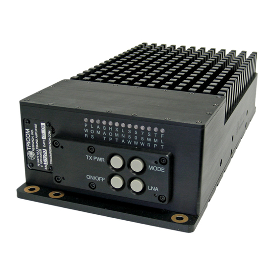
Controls, Indicators, and Connectors The TCR-MBA-75 NBT has push Button switches to control: On/ Off (Bypass) Transmit power selection (35, 50 or 75 Watts – SATCOM only) Operational mode (SATCOM, LOS, LOS AM, FHOP, FHOP AM) DC Power (amplifier bypass to LOS power in off) There are also several status indicators on the Amplifier's front panel as shown in Figures 2-1. -
Page 12: Operational Procedures
Table 2-1. TCR-MBA-75 NBT Controls, Indicators, and Connectors Operational Procedures 2.3.1 General Information The TCR-MBA-75 NBT can be used for operation once it has been installed as described in Section 3. 2.3.2 Equipment Set-up Refer to Paragraph 2.2 for the locations and functional description of the controls and indicators. -
Page 13: Mbitr Specific Operation
2 seconds. The ON/OFF push button switch cycles the TCR-MBA-75 NBT from power On to power Off Bypass mode. In Power Off Bypass the RF is automatically routed to the LOS antenna port directly from the transceiver. -
Page 14: Remote Operation
Radio input connector on the amplifier (refer to figure 2-5). To power on the TCR-MBA-75 NBT the ON/Off switch on the Bias Tee must be in the On position and then the user must also press the ON/OFF button on the TCR- MBA-75 NBT for approximately 2 seconds. -
Page 15: Out Of Band Operation
Figure 2-5. Remote Operation Setup 2.3.3.4 Out of Band Operation Operating outside of the UHF SATCOM frequency bands with the SATCOM mode selected will cause an alarm to occur. Returning to the receive mode will clear the transmit frequency fault alarm. Operating on SATCOM frequencies while in the LOS mode with an antenna connected to the LOS port will not cause an alarm and it will operate properly, however, the amplifier will not comply with the timing requirements for DAMA operation. -
Page 16: Installation General Information
INSTALLATION General Information This section contains information necessary for preparing the TCR-MBA-75 NBT for use. Preparation for Use After unpacking the system and inspecting for physical damage, select an appropriate location for the Amplifier. Although the Amplifier is weather-resistant, placing it in a location where it is protected from direct salt spray, rain, and sunlight will increase its service life. -
Page 17: Table 3-1 Dc Input Power Connector Pin Out
mode with the push button Mode switch. RF output is routed to the appropriate Antenna connection determined by the mode selected. Figure 3-1 Amplifier DC input connector Pin # Connection Pin A +28V DC (positive) Pin B +28V DC (positive) Pin C Ground (negative return) Pin D... -
Page 18: Figure 3-2 Amplifier Mounting Dimensions
Figure 3-2 Amplifier Mounting Dimensions 14 | P a g e...
Need help?
Do you have a question about the TCR-MBA-75 NBT and is the answer not in the manual?
Questions and answers