Table of Contents
Advertisement
Quick Links
Advertisement
Table of Contents

Related Manuals for Elsys AE-Amp MK II


Summary of Contents for Elsys AE-Amp MK II
- Page 1 AE-Amp Acoustic Emission Amplifier MK II User Manual AE-AMP Boxed AE-Amp Rack...
- Page 2 Thank you! • Installation (Over voltage) • Category II (Main Supply Connector) and Thank you for purchasing Elsys AE Measure- Category I (Measuring Terminals) ment Equipment. • Pollution Degree 2 For more information, please visit •...
-
Page 3: Table Of Contents
3.5 LED Indication .............6 4. HV Pulse Generator ..........7 4.1 Signals ................7 4.2 Pulse Pattern Generator ........8 5. Software ..............9 5.1 Driver Download ............9 5.2 Amplifier Settings ............9 5.3 HV Pulser ..............10 6. Specification ............11 Elsys AG AE-Amp User Guide... -
Page 4: Overview
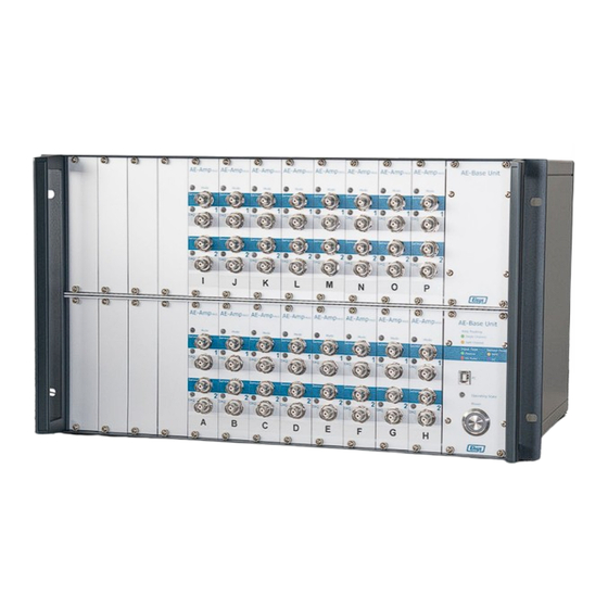
Two different Base Unit chassis available: Amp-BU-24-AE (for up to 12 modules / 24 channels) Amp-BU-48-AE (for up to 24 modules / 48 channels) • USB interface (emulated COM port) for accessing all installed amplifiers (Internally over RS485) AE-Amp User Guide Elsys AG... -
Page 5: Architecture
AE-Base-Unit Box variant only CH 2 IEPE 5VDC 28VDC Signal In Gain: 0 dB RS485 20 dB 40 dB Signal Out 60 dB AE-Amp Hardware Architecture of a full AE-Amp, Base Unit, HV Pulser System Elsys AG AE-Amp User Guide... -
Page 6: Mode Of Operation
The front LED is red when the pass-through mode is activat- ed. Activation is done over software. The applied voltage to the sensor is also passed to the amplifier output attenuated by 100. AE-Amp User Guide Elsys AG... -
Page 7: Hv Pulse Generator
The second signal is normally fed to a digital input of the DAQ to distinguish HV pulses from passive AE events. • Input: high voltage input which is multi- plexed to a sensor/actuator. Elsys AG AE-Amp User Guide... -
Page 8: Pulse Pattern Generator
(see Sequence Diagram) Pulse Interval Time period between each pulse [ms] on the same channel Chn. Delay Delay between the last pulse on one channel until a new pulse on a second channel is applied AE-Amp User Guide Elsys AG... -
Page 9: Software
Alternatively, a tool for operation can be pro- grammed yourself via the serial interface using the programming instructions. 5.1 Driver Download Download the drivers for the USB to RS485 converter chip directly from the FTDI web-site: http://www.ftdichip.com/Drivers/VCP.htm Elsys AG AE-Amp User Guide... -
Page 10: Hv Pulser
HV pulses are to be sent can be added. Pulse generation can be started or stopped using the Start/Stop button. The program must remain open for the se- quence to run. AE-Amp User Guide Elsys AG... -
Page 11: Specification
12 V DC, max 8 W 110 - 240 V AC, max 75 W Interface USB (emulated COM Port) Dimensions 108 x 45 x 170 mm Amp-BU-24-AE: 19’’ x 3U x 32.5cm Amp-BU-48-AE: 19’’ x 6U x 32.5 cm Elsys AG AE-Amp User Guide... - Page 12 File Revision: Date Description 27.05.2024 Manual Update MK2 AE-Amp User Guide Elsys AG...
Need help?
Do you have a question about the AE-Amp MK II and is the answer not in the manual?
Questions and answers