
Related Manuals for Elsys SGA-2


Summary of Contents for Elsys SGA-2
- Page 1 Strain Gauge Amplifier User Manual Elsys AG Mellingerstrasse 12 +41 56 496 01 55 CH-5443 Niederrohrdorf www.elsys-instruments.com...
-
Page 3: Table Of Contents
Configuration ....................... 11 Internal Quarter Bridge Resistor R4 ..............12 Safety Information (Base Unit EL-SGBU only) ............13 Base Unit EL-SGBU Specifications ................14 Specifications of the SGA2-Box MK2 ............... 14 Amplifier Specifications ................... 15 Notes ........................16 © Elsys AG 1/18... -
Page 4: Overview
Strain Gauge Amplifier User Manual V2.0 1 Overview The Strain Gauge Amplifier SGA-2 is designed as a differential front-end amplifier to connect full, half or ¼ bridge strain gauges with internal bridge completion. Applications: • Deformation testing for material characterization •... -
Page 5: Cable Pin Assignment
Strain Gauge Amplifier User Manual V2.0 2 Cable Pin Assignment Elsys Instruments SGA cable assembly with LEMO circular push pull connectors, straight plug male with cable collet. CLAD72 defines the maximum outer cable diameter, e.g. 7.2mm. Connector type Lemo part number 16 pin Lemo FGG.2B.316.CLAD72... -
Page 6: Operating Modes, Block Diagrams
Full Bridge at the end, either externally in the sensor, the Load Cell, or in combination with the internal Half- and Quarter Bridge. Sensor Int. Half Bridge Int. Quarter Bridge R4 Full Bridge Disabled Not assembled Half Bridge Enabled Not assembled Quarter Bridge Enabled assembled 3.1 Full Bridge © Elsys AG 4/18... -
Page 7: Half Bridge
Strain Gauge Amplifier User Manual V2.0 3.2 Half Bridge 3.3 Quarter Bridge © Elsys AG 5/18... -
Page 8: Configuration And Settings
4 Configuration and Settings Each SGA module can be configured by its on-board dip-switches or with the free availa- ble SGA 2.0 configuration software. Please contact your distributor or Elsys Instruments directly to get a copy of this application: info@elsys-instruments.com... -
Page 9: Software Settings
Please note that the live value or GETADC return value has a precision of approx. 2% and is meant to see a trend or position of a sensor or measurement. For high speed and high resolution, an Elsys DAQ system is required. 4.3.1 AppConfig.xml... -
Page 10: Connectors And Configuration
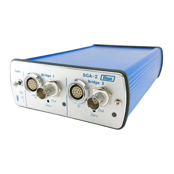
Figure 3: Front view SGA2-Box 5.2 Rear View The SGA-2 will be powered with an external 12V power supply. There is a 4mm con- nector for earthing, a USB type B socket for PC connection and a phoenix connector as an external calibration input. -
Page 11: Calculations
;Amplifier Gain S[mV/V] = 10 ; Sensitivity LR[Kg] ; Rated Load L[Kg] = 0.5 ; Applied Load Vex[V] = 10 ; Excitation Voltage Vout[mV] = L/LR ; Calculate the applied load from the output voltage Load Vout © Elsys AG 9/18... -
Page 12: Open Sga Box Enclosure
6 Open SGA Box Enclosure In case of changing the Dip-Switch settings, the SGA boxed version has to be opened. Please note that all settings can be done with the Elsys SGA 2.0 Tool. Necessary tools: T8 Torx or star screwdriver Remove the connector for external calibration on the rear side. -
Page 13: Sga2 Mk2 Module
Half Bridge. The fourth DIP switch is not used at the moment. The rotary switch defines the board address. This will be set to "0" for boxed devices. For rack version, the board address will be defined according its position in the rack. Figure 7: Configuration settings © Elsys AG 11/18... -
Page 14: Internal Quarter Bridge Resistor R4
There are two screw terminals, one for each channel, for assembling the internal Quarter Bridge R4 Resistor. This will be necessary in case of using a Quarter Bridge sensor. The resistance of R4 has to match the one of the used sensors. Figure 8: 1/4 Bridge Resistor R4 © Elsys AG 12/18... -
Page 15: Safety Information (Base Unit El-Sgbu Only)
Lethal voltages exist inside the instrument. Only qualified technicians of supplier staff are authorised to open the case of the Base Unit. Otherwise warranty will be lost! Always ensure that power cord is removed before opening the case. © Elsys AG 13/18... -
Page 16: Base Unit El-Sgbu Specifications
10 Specifications of the SGA2-Box Case Aluminium case approx. 110x45x185 mm (WxHxD) Number of channels per box Power Supply 12 VDC, max. 700mA By a Mains Adapter 100 to 240 VAC, 50/60Hz Weight 0.65 kg (incl. Mains Adapter) © Elsys AG 14/18... -
Page 17: Amplifier Specifications
Internal ½ Bridge Asymmetry Connector Type Input max. ±0.1% (= 10 mV @ 10V) Lemo 16pol. Model FGG.2B.316.xx Lemo 7pol. Model FGG.1B.307.xx Power Supply Lemo 6pol. Model FGG.1B.307.xx 12 Vdc ±10%, max. 5 W per 2 Ch © Elsys AG 15/18... -
Page 18: Notes
Strain Gauge Amplifier User Manual V2.0 12 Notes © Elsys AG 16/18... - Page 19 Strain Gauge Amplifier User Manual V2.0 © Elsys AG 17/18...
- Page 20 Strain Gauge Amplifier User Manual V2.0 Document information Filename: SGA2 MK2 Manual EN.docx Status: Released Last modification Date: 19.02.2020 Author: Andreas Boillat / Thomas Berger © Elsys AG 18/18...
Need help?
Do you have a question about the SGA-2 and is the answer not in the manual?
Questions and answers