Table of Contents
Advertisement
IMPORTANT:
◎Do not operate this dust collector before reading this manual.
◎Only those who fully understand the contents of this manual should operate this dust collector.
◎Carry out daily and periodic inspections, observing all operation and maintenance instructions
given in this manual.
◎Observe all applicable laws regulation regarding the installation and maintenance of the dust
collector.
INTELLIGENT DUST COLLECTOR
OPERATION MANUAL
PiE
SERIES
2014.7
Advertisement
Table of Contents

Related Manuals for Amano PiE Series


Summary of Contents for Amano PiE Series
- Page 1 INTELLIGENT DUST COLLECTOR SERIES OPERATION MANUAL IMPORTANT: ◎Do not operate this dust collector before reading this manual. ◎Only those who fully understand the contents of this manual should operate this dust collector. ◎Carry out daily and periodic inspections, observing all operation and maintenance instructions given in this manual.
- Page 2 ■Important Information on Safety Safe notes described in this manual are designated as follows,depending on the levels and contents. Please read this information thoroughly before using the product. This symbol indicates mishandling in which a dangerous condition may DANGER : !...
- Page 3 Also, make sure to keep the manual close at hand so that you can refer to it when necessary. ● The PiE Series Dust Collector is intended for collecting particles that do not pose the risk of dust explosion or fire.
-
Page 4: Table Of Contents
CONTENTS 1. For Safe Operation .......................... 4 Cautions regarding installation ....................7 2. Structure and Names of Components ..................... 8 3. Preparing for Operation........................11 (1) Installing ducting ......................... 12 (2) Connecting the power supply ....................13 (3) Connecting the compressed air supply ................. 14 (4) Connecting the manometer (For J type only) ................ -
Page 5: For Safe Operation
1. FOR SAFE OPERATION Before operating the dust collector, read the following warnings and cautions, and make sure you understand them. WARNING ! Do not suck the following materials. ・Explosive material … Such as aluminum, magnesium, titanium, epoxy, flour, toner. ・Flammable materials ……... - Page 6 WARNING ! If a fire occurs or there is a dust explosion inside the dust collector ・turn off the power immediately. ・use a fire extinguishing agent suitable for dust. ・even after the fire is out, don’t open the door until the internal temperature drops to the normal level.
- Page 7 CAUTION ! Do not suck the following materials. ・Sticky substances …………Soluble mist, oil mist, etc. ・Other materials ……………Fluid, such as water and oil. If ignored, the performance may be deteriorated. Always wear protective clothing (such as gloves, mask, protective glasses, dustproof clothing) when discharging dust and inspection.
-
Page 8: Cautions Regarding Installation
CAUTIONS REGARDING INSTALLATION Satisfy the following conditions when installing this dust collector. Failure to do so will prevent the dust collector from functioning normally and may cause a breakdown of the product, which could lead to accidents to occur. ・... -
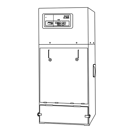
Page 9: Structure And Names Of Components
2. STRUCTURE AND NAMES OF COMPONENTS BODY Exhaust port Control panel Motor Diaphragm valve (with pilot valve) Blow tube Suction port Handle ( at two places on the Header pipe left and right side) Filter Inspection cover Filter Bucket cover Bucket Lift panel Bucket lift handle... - Page 10 Control panel ① ② ③ ④ ⑤ The drawing on the right shows a message window on the “J” type machine control panel (Without “ Q / ⊿P / Ps / I ” display). Part name Function This lamp goes ON when the power cord is connected to the primary POWER lamp ①...
- Page 11 KEY-SWITCHS / LAMPS ON THE CONTROL PANEL ① ② ④ ⑥ ⑦ ③ ⑤ ⑧ ⑨ Part name Function Use this key to change the mode of display in the message window. DISP CHANGE key ① Each time this key is pressed, the next message is displayed in the window.
-
Page 12: Preparing For Operation
3. PREPARING FOR OPERATION Make sure to read and understand the following warnings and cautions when preparing for the operation of the dust collector. WARNING ! Never install the dust collector at or near hazardous areas forbidden by laws and regulations. -
Page 13: Installing Ducting
■ Installation Precautions Please follow all precautions given below when using this dust collector. Otherwise, you will not have the full performance of the dust collector, or even may suffer from malfunctions, which could lead to causing an accident to occur. •... -
Page 14: Connecting The Power Supply
(2) Connecting the Power Supply CAUTION • Connect the power cord to a 3-phase power supply following the steps given below. Make sure the specifications of the power supply to be used meet the requirements given on the identification plate affixed to the body unit. Power supplies of different specifications must not be used for this machine. -
Page 15: Connecting The Compressed Air Supply
<Check on rotation direction> Operate the fan to check it the motor rotates in the proper direction. Give a push to the [ON] switch to start to fan rotation. Immediately, turn on the [OFF] switch. When the fan slows down, you can see in which direction the fan motor rotates. -
Page 16: Connecting The Manometer (For J Type Only)
(4) Connecting the Manometer (For J Type only) The evaluation of filter clogging is made on the differential pressure of the suction air between before and after-filtration. If the differential pressure is large, the filter should have got clogged. The manometer is used to measure this differential pressure. -
Page 17: Setting For Remote-Operation
(5) Setting for Remote-Operation In addition to the operation with switches on the control panel, a remote operation through external signals is also possible with this machine. If you desire to operate the machine from a remote location, make the following connections. -
Page 18: Setting The Data
4. SETTING THE DATA Before running the machine, users should make settings for certain functions as follows from the control panel. This chapter mainly relates to settings for pulse jet operation (filter dust removal operation). Setting items should vary by the type of machines (U, M, J). See the table below. Note: Settings for remote control (at page 25) must be made before starting operation. -
Page 19: Airflow Setting
Item Content Function In addition to the operation with switches on the control panel, a Remote remote operation through external signals is also possible with n-06 ○ ○ ○ operation this machine. If you desire to perform remote operation, make this setting valid. -
Page 20: Setting The Pulse Starting
(2) Setting the pulse starting U M Clogged filter will cause a decrease in the volume of air intake. Here, the setting is made to perform automatic removal of the dust (pulse operation) from dust accumulation on the filter surface that is the cause for lowering of air intake efficiency. -
Page 21: Setting The Pulse Jet Operation Mode
(3) Setting the pulse jet operation mode U M J This setting is made to select a mode of filter dust removal operation. ① Press the DISP CHANGE key several times to locate ▲ just under “Mode”. ② The setting item “n-00” appears on the display. If not, continue pressing on keys until the target item appears. -
Page 22: Setting "On Time
(4) Setting “ON TIME” U M J This sets the continued operating time of automatic dust removal (pulse operation). The setting is made effective when the pulse mode, explained in the previous page, is set to “001”, “002”, or “003”. ①... -
Page 23: Interval
⑤ Press the SET key or leave the screen as it is for 10 seconds. The screen will return to the previous screen (with prompt “n-02” displayed). If you desire to continue updating “n-03” and the subsequent items, select the next target item number with keys. -
Page 24: End Pulse
(7) End pulse U M J This setting enables the dust removal operation to be performed at the time the dust collector stops running. Set the desired number of cycles of that operation. ① Press the DISP CHANGE key several times to locate ▲... -
Page 25: Setting The Pulse Stop Target Differential Pressure
(8) Setting the pulse stop target differential pressure U M This setting enables automatic stop of the pulse jet operation. Enter the amount of filter differential pressure to be deducted from the pulse-jet-operation starting differential pressure value in order to effect pulse-jet-operation stop. -
Page 26: Setting The Remote Operation
(9) Setting the remote operation U M J This equipment can be operated not only by switches on the control panel, but remotely by external signals. For the remote operation, the system needs to be set up accordingly. In an outdoor type model, the remote operation mode is set as default, and such setting must not be changed unless a special instruction is made by the maker. -
Page 27: Setting The Abnormal Filter Differential Pressure
(10) Setting the abnormal filter differential pressure U M If the filter differential pressure increases exceedingly, an error indication (Er 13) is given on the display. Specify the set point at which the error display is started. The initial value has been set to 2400 Pa. If the error indication is displayed repeatedly even after the execution of the pulse operation, it should be taken as an indication of the time for filter replacement. -
Page 28: Other Settings
(11) Other settings Do not make change in settings for the items “n-07” and the subsequent (for n-08, see the description in the previous section). A wrong setting in any of these may impede proper operation of the safety device (operational fault/error detection device). When you make a mistake in setting operation, do not press the ENTRY key, but press the SET key to change the screen back to the “DISPLAY SELECTION”... -
Page 29: Operation
5. OPERATION Make sure to read and understand the following warnings before operating the dust collector. WARNING ! Do not suck the following materials. ・Explosive material … Such as aluminum, magnesium, titanium, epoxy, flour, toner. ・Flammable materials …… Such as gasoline, thinner, benzene, kerosene, paint. ・Dust containing sparks …... -
Page 30: Start And Stop Of The Operation
CAUTION ! Do not suck the following materials. ・Sticky substances …………Soluble mist, oil mist, etc. ・Other materials ……………Fluid, such as water and oil. If ignored, the performance may be deteriorated. Do not operate the dust collector with the suction and exhaust ports closed or blocked. Such operation may cause an overheating, resulting in the occurrence of a fire. -
Page 31: Changing The Display Content
(2) Changing the Display Content During the operation, the message window displays various contents that can be changed in order each time the [DISP CHANGE] key is pressed. Display Content Remarks Q Air flow Available only for U/M type. /min) (m Differential between the two static pressures... -
Page 32: Message Display
• DIP switch setting has been changed on the circuit board. Model setting Er05 ○ ○ ○ → Contact Amano or your dealer of Amano’s representative for the revised setting guide and follow the given instructions. • An external signal alarm is generated. Er07 External error 1 △ △... - Page 33 List of Message Display (When INSPECT lamp is lit) Display Alarm content Corrective action U M J • Fault in the inverter (for U type) → Check the inverter for any fault. Er09 ○ ○ ○ Fan (overload) • Overload to fan motor. (for M/J type) →...
-
Page 34: Dust Removal From The Filter
(4) Dust Removal from the Filter Press the [PULSE] switch on the control panel to carry out dust removal from the filter. CAUTION • Before pressing the PULSE switch, make sure the filter inspection cover is closed. If the switch should be pressed with the door open, the dust removed off the filter by the pulse jet would scatter outwards through that opening. -
Page 35: Reset Of Thermal Relay
CAUTION • In cases the dust collector cannot be restored to normal operation by resetting, or current interruption is often caused by the trip of thermal relay, contact Amano, or your dealer of Amano representative. • If the cause of the thermal relay trips should be attributable to any other factors than this machine, conduct an on-the-spot current/voltage investigation by the qualified electrician on your side. -
Page 36: Maintenance
6. MAINTENANCE Make sure to read and understand the following warnings and cautions before performing maintenance. DANGER ! Never operate the machine with its cover removed. This could cause serious injury. Never insert your hands into the rotary unit area. This could cause serious injury. -
Page 37: Discharging The Collected Dust
(1) Discharging the Collected Dust [ Standard bucket type ] At the end of every working day, the collected dust should be discharged from the dust collector inside. If this caution is not observed and an ignition source is put in the accumulation of dust, a fire can be caused to occur. The discharged dust, then, should be disposed of appropriately according to your in-company rule or the related local regulations. - Page 38 Method to install the dust pack Dust pack Turn down outward Method to install the lift handle. Front side of machine Rear side of machine Lift handle Groove Groove Lift handle Insert the lift handle into the groove on the front side of the machine while inserting the lift handle into the groove on the rear side of the machine.
- Page 39 ⑧ Turn up the bucket lift handle to the left to secure the bucket. ⑨ Fit the hole in the bucket cover to the bucket cover receiver of the main frame. ⑩ While pressing the bucket cover against the main frame, secure it with the catch clips.
- Page 40 [Notes on the rotary valve type] If the equipment is equipped with the automatic discharge device "rotary valve", be sure not to put your hands in the spinning portion of the rotary value during operation. Ignoring it results in a serious injury. Important! The discharge pipe is provided with a metal grating for safety.
-
Page 41: Inspection And Replacement Of Filter
(2) Inspection and Replacement of Filter The filter should be periodically inspected and replaced. The standard interval between replacements is 1 to 1.5 years. (Subject to change depending on the kind, size of the dust to be collected, and machine’s working environment. - Page 42 ⑧ While holding up the filter frame, secure it with the wing nut. If the wing nuts are not tightened sufficiently, the dust may leak. ⑨ Insert the hook on the cover support of the main frame Hook in the hole in the filter inspection cover. Note: ・Hold the filter inspection cover by grasping both handles and put it on the cover support.
-
Page 43: Maintenance Of Dust Removal Components
⑩ While pressing the filter inspection cover against the main frame, secure with the star knob bolt. Note: ・secure the inspection cover with star knob bolts while holding the cover against the main body with the hand to avoid the fall of the cover. Important: ・... - Page 44 • The maintenance of the diaphragm valve (with pilot valve) needs to be carried out one or two times a year. • The diaphragm (rubber portion) valve is a consumable part. It should be replaced regularly once every year. • For further information, contact Amano, or your dealer of Amano representative. Diaphragm valve...
-
Page 45: Appendix
7. APPENDIX SPECIFICATIONS Model name PiE-15 PiE-30 PiE-45 PiE-60 M・J type 3-phase,200V,50 or 60Hz for exclusive-use ; V and Hz as per nameplate Power supply U type 3-phase,200V,50 or 60Hz shared-use ; V and Hz as per nameplate (Point) Airflow Performance... -
Page 46: Service Parts
SERVICE PARTS Name Part Number Remarks Standard filter PIB-210070 with the Filter packing Finefil filter PIB-213070 with the Filter packing ※ Anti-static filter PIB-220070 with the Filter packing ※ OW filter PIB-219070 with the Filter packing ※ Filter packing PIB-211300 Urethane sponge Diaphragm valve (with pilot valve) -
Page 47: Outside Drawing
OUTSIDE DRAWING PiE-15 Drawing is common for U, M and J types --- A manometer is attached only to J type. PiE-30 Drawing is common for U, M and J types --- A manometer is attached only to J type. - Page 48 PiE-45 Drawing is common for U, M and J types --- A manometer is attached only to J type. PiE-60 Drawing is common for U, M and J types --- A manometer is attached only to J type.
-
Page 49: Wiring Diagram
WIRING DIAGRAM PiE M type The above are wiring diagram for standard dust collectors for domestic use; the dust collectors built for special use or foreign use may have different data from above in the contents. Refer to the machine number plate for the power supply voltage and frequency. - Page 50 PiE J type The above are wiring diagram for standard dust collectors for domestic use; the dust collectors built for special use or foreign use may have different data from above in the contents. Refer to the machine number plate for the power supply voltage and frequency.
- Page 51 PiE U type The above are wiring diagram for standard dust collectors for domestic use; the dust collectors built for special use or foreign use may have different data from above in the contents. Refer to the machine number plate for the power supply voltage and frequency.
-
Page 52: Troubleshooting
TROUBLESHOOTING To ensure safety, if a fault or error is detected during operation, turn off the power supply before everything. After that perform inspection. If repairs are needed, contact your dealer of Amano representative. Cause Remedy Trouble/problem The ON (START) switch •... -
Page 53: Periodic Inspection Table
The motor needs inspection and maintenance service every 2 or 3 years of operation. Motor Contact Amano, or your dealer of Amano’s representatives. ABOUT DISPOSAL OF THE PRODUCT When disposing of the dust collector, attempt it appropriately by observing related laws and bylaws of... - Page 56 275 Mamedocho Kohoku-ku, Yokohama, Japan 222-8558 TEL.:+81-45-401-1441 FAX.:+81-45-439-1150 http://www.amano.co.jp/English PKA 911010 (14) Printed in Japan T8704A...
Need help?
Do you have a question about the PiE Series and is the answer not in the manual?
Questions and answers