Table of Contents
Advertisement
Quick Links
Advertisement
Table of Contents

Related Manuals for Credo 3500KG GVM

Summary of Contents for Credo 3500KG GVM
- Page 1 USER MANUAL Read instructions before installation NZ: 3500KG GVM | AU: 4500KG GVM...
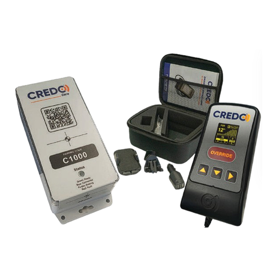
- Page 2 What is the Credo? The Credo Core represents the next evolutionary stage of the Credo Brake controller. True to its heritage, this controller harnesses the fundamental essence of the Credo brake controller. Dedicated to operating electric drum brakes, The Credo Core has been refined to be a cost effective solution for trailers with 1 to 3 electric braked axles.
-
Page 3: Table Of Contents
Index Page 3-7 OPERATION Remote Overview _______________ 3 Remote Screens ________________ 4 Remote Operation ______________ 5-6 Operation Setup ________________ 7 Page 8-9 CONTROLLER Controller Overview _____________ 8 Mounting Requirements __________ 8 Controller Dimensions ____________ 9 Page 10-15 INSTALLATION Mounting Requirements __________ 8 Wiring Requirements _________ 10-11 Auxiliary Power _________________ 11 Wiring Diagrams _______________ 12-15... -
Page 4: Operation
Connection Statis Indicator: Orange LED shows connection status - Flashing indicates searching - Steady indicates connected OLED Screen: Displays settings and menus for Credo operation. Over-ride Button: Override brakes engage 75% of gain. Up / Down Buttons: Used for screen navigation and adjusting setting values. -
Page 5: Remote Operation
Remote Operation Braking Level Settings Braking levels are adjusted with 2 settings. Gain Adjust the gain to set the max- imum braking output level. The minimum level is 5% and the maximum level is 99%. The level changes in steps of 5. Sensitivity Adjust the sensitivity to increase the rate at which the brakes are... - Page 6 System Menu: System Menu To enter press and hold up and down buttons at the > Change I.D. same time for more than 5 seconds Trailer Diag. Remote Info Change ID Screen: Check the wireless signal strength and recode the ID to match the controller to connect to.
-
Page 7: 24V Operation Setup
24v Operation Setup The Credo Core can operate with 24V vehicles but actual compatibility of the trailer with a 24V tow vehicle is determined by all the components on the trailer including lights and breakaway battery. -
Page 8: Controller Overview
Controller Overview Aerial Location: Internally mounted aerial. Covering with metallic objects may reduce signal strength Serial Number: Program remote to match this serial when pairing. Status LED: GREEN = Ready BLUE = Connected PURPLE = Braking RED = Fault Connector: Wiring loom connector in back of controller. -
Page 9: Controller Dimensions
Controller Dimensions Freephone 0800 487 245 sales@trailparts.co.nz www.trailparts.co.nz... -
Page 10: Wiring Requirements
Wiring Requirements To ensure adequate power is available for the brakes installed on the trailer refer to the table below. Make sure the brake power requirements are more than adequately met by the supplied power on the right of the table. Using auxiliary sources gives redundancy to ensure that operation is always consistent and effective even if that is more power than required. -
Page 11: Auxiliary Power
Wiring Size Requirements When choosing the size cables you use take into account the voltage drop on the cables. Using a conductor that is large enough for the current capacity is enough for small trailers but on larger trailers will cause too much voltage drop and reduce performance. -
Page 12: Wiring Diagrams
Connector Wiring Diagram Brakes Out (Common Output) Earth Not Required - Future use Earth Stop Lights in Not Required - Future use Earth Tail Lights in Earth Aux Power 1 (Battery) Aux Power 2 (Battery) View from back of connector Freephone 1300 538 598 sales@trailparts.com.au... - Page 13 Junction Box Diagram RH Indicator Tail Lights Brakes Out Service Brakes Brakes Out Earth Auxiliary Earth Not Connected Earth Stop Lights in Stop Lights Earth Not Connected LH Indicator Tail Lights in Earth Aux Power 1 (Battery) Aux Power 2 (Battery) View from back of connector Freephone 0800 487 245...
- Page 14 7-pin Wiring Diagram Brakes Out Trailer Brakes Out wiring Earth Not Required - Future use Earth Stop Lights in Earth Not Required - Future use Tail Lights in Earth Aux Power 1 (Battery) Aux Power 2 (Battery) View from back of connector Freephone 1300 538 598 sales@trailparts.com.au...
- Page 15 12-pin Wiring Diagram Brakes Out Trailer Brakes Out wiring Earth Not Required - Future use Earth Stop Lights in Not Required - Future use Earth Tail Lights in Earth Aux Power 1 (Battery) Aux Power 2 (Battery) View from back of connector Freephone 0800 487 245 sales@trailparts.co.nz...
-
Page 16: Troubleshooting Controller Status Indicator
Staus Indicator - Controller The LED on the controller indicates the staus of the Credo Core. Description Green Ready Blue Connected Purple Braking Fault Faults / Error Codes Fault Parameter Description Code Controller has detaected a low voltage. Input voltage low Check trailer plug and connections to confirm voltage on diagnotic screen. -
Page 17: Warranty
LIMITED 18 MONTH WARRANTY CONDITIONS Trailequip Ltd warrants that the mechanical and electrical components of the TRAILPARTS/CREDO products as listed below will be free of defects in material and workmanship for a period of eighteen months from the original date of purchase. - Page 18 Notes: Freephone 1300 538 598 sales@trailparts.com.au www.trailparts.com.au...
- Page 19 Freephone 0800 487 245 sales@trailparts.co.nz www.trailparts.co.nz...
- Page 20 AU Freephone 1300 538 598 NZ Freephone 0800 487 245 sales@trailparts.com.au sales@trailparts.co.nz www.trailparts.com.au www.trailparts.co.nz...
Need help?
Do you have a question about the 3500KG GVM and is the answer not in the manual?
Questions and answers