
Related Manuals for Reflex Hydroflow XS

Summary of Contents for Reflex Hydroflow XS
- Page 1 Reflex Hydroflow Mains Water Station Original operating manual www.reflex-winkelmann.com...
-
Page 3: Table Of Contents
Contents English Reflex Hydroflow Mai ns Water Station Contents Notes on the operating manual ......................5 Liability and guarantee ........................5 Safety ..............................6 Explanation of symbols ............................ 6 3.1.1 Symbols and notes used ........................6 Personnel requirements ..........................6 Personal protective equipment ........................ - Page 4 Contents 11.1 Conformity and standards ..........................31 11.2 Guarantee ..............................31 4 — English Reflex Hydroflow Mains Water Station —...
-
Page 5: Notes On The Operating Manual
This operating manual is an important aid for ensuring the safe and reliable functioning of the device. Reflex Winkelmann GmbH accepts no liability for any damage resulting from failure to observe the information in this operating manual. In addition to the requirements set out in this operating manual, national statutory regulations and provisions in the country of installation must also be complied with (concerning accident prevention, environment protection, safe and professional work practices, etc.). -
Page 6: Safety
Use the prescribed personal protective equipment as required (e.g. ear protection, eye protection, safety shoes, helmet, protective clothing, protective gloves) when working on the system. Information on personal protective equipment requirements is set out in the relevant national regulations of the respective country of operation. 6 — English Reflex Hydroflow Mains Water Station —... -
Page 7: Intended Use
Risk of burns on hot surfaces Hot surfaces in heating systems can cause burns to the skin. • Wear protective gloves. • Please place appropriate warning signs in the vicinity of the device. Reflex Hydroflow Mains Water Station — English — 7... - Page 8 Equipment parts with a safety function in respect of water-side pressure limiting according to the Pressure Equipment Directive 2014/68/EU and temperature limiting according to the Pressure Equipment Directive 2014/68/EU are not supplied. The operator is responsible for on-site provision of water-side pressure and temperature protection. 8 — English Reflex Hydroflow Mains Water Station —...
-
Page 9: Description Of The Device
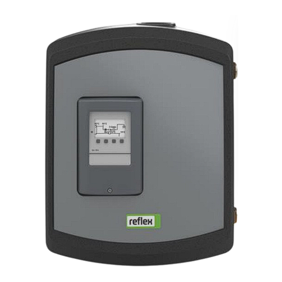
Hydrow The Reflex Hydroflow mains water station XS, S, M, L and XL provides hot potable water on demand. The station does not store hot water, but heats it using the counterflow principle via a heat exchanger that physically separates the heating water from the buffer tank and the potable water. -
Page 10: Identification
Type code Type code (example) Device size (XS to XL) CU = Stainless steel heat exchanger with copper solder Reflex Hydroflow XS - CU SST = Stainless steel heat exchanger with stainless steel solder DW = Double-walled (copper soldered) 10 — English... -
Page 11: Function
The controller is a thermostatic controller. The hot water temperature is set via a thermostatic head. For Hydroflow S and Hydroflow M The controller is a electrical controller. The electrical controller is set via the integrated control panel. Reflex Hydroflow Mains Water Station — English — 11... - Page 12 The volume flow sensor records the volume flow of heated potable water. The temperature probe detects the temperature of the potable water. Control mode The controller is a electrical controller. The electrical controller is set via the integrated control panel. 12 — English Reflex Hydroflow Mains Water Station —...
-
Page 13: Scope Of Delivery
• Ball valve set (only Hydroflow XL) Optional equipment and accessories Compatible accessories can be found in the currently valid price list. Note! Separate operating instructions are supplied with accessories. Reflex Hydroflow Mains Water Station — English — 13... -
Page 14: Technical Data
IP Protection class IP44 IP44 IP44 IP44 IP44 Permissible ambient temperature 5 - 45 °C 5 - 45 °C 5 - 45 °C 5 - 45 °C 5 - 45 °C 14 — English Reflex Hydroflow Mains Water Station —... - Page 15 Technical data Pressure loss on secondary side Flow rate: (l/min) Reflex Hydroflow Mains Water Station — English — 15...
-
Page 16: Chemical Data
Total hardness 4 - 14 [Ca ; Mg ]/ [HCO ] > 0.5 4 - 14 [Ca ; Mg ]/ [HCO ] > 0.5 Total organic carbon < 30 mg/l No requirement 16 — English Reflex Hydroflow Mains Water Station —... -
Page 17: Installation
Bruising from falls or bumps on system components during installation. • Wear personal protective equipment (helmet, protective clothing, gloves, safety boots). Note! Contract an authorised specialist company for installation, commissioning and maintenance. Reflex Hydroflow Mains Water Station — English — 17... -
Page 18: Installation Conditions
Pipelines must be connected so there are no residual forces and torques and must be routed so they are free from vibrations. • If necessary, provide support structures for the pipelines or equipment. • If you have any questions, please contact Reflex After Sales & Service. Proceed as follows for the installation: 1. Position the mains water station. –... -
Page 19: Positioning
2. Now insert a screw with washer and mounting element and turn the screw until the screw head is 35 mm from the wall. 3. Mount the station. Align the station horizontally and secure it with a second screw and a washer. 4. Tighten both screws evenly. Reflex Hydroflow Mains Water Station — English — 19... - Page 20 Installation Mounting the hot water storage tank Note! The assembly instructions of the hot water storage tank connection set is included with the corresponding accessories. Hydroflow XS-M Hydroflow L-XL 20 — English Reflex Hydroflow Mains Water Station —...
-
Page 21: Hydraulic Connection
Pipelines must be connected so there are no residual forces and torques and must be routed so they are free from vibrations. • If necessary, provide support structures for the pipelines or equipment. • If you have any questions, please contact Reflex After Sales & Service. ATTENTION Damage to sensors Opening the volume flow suddenly can damage the sensor. - Page 22 Installation Connection to the system Hydroflow XS-M Hydroflow L-XL Cold water Buffer lead Hot water Buffer return 22 — English Reflex Hydroflow Mains Water Station —...
-
Page 23: Electrical Connection
The mains water station is completely pre-assembled and pre-wired at the factory. Connect the mains cable for commissioning. Installation and commissioning certificate Note! The installation and commissioning certificate can be found at the end of the operating manual. Reflex Hydroflow Mains Water Station — English — 23... -
Page 24: Commissioning
The water connections to the system circuit are established. • The system circuit is filled with water and gas-vented. • The electrical connection has been created according to applicable national and local regulations. 24 — English Reflex Hydroflow Mains Water Station —... -
Page 25: Leak Testing
The heating system including the primary side of the mains water station must be filled in accordance with VDI 2035. Vent the system completely. Note! The commissioning process is now concluded. Reflex Hydroflow Mains Water Station — English — 25... -
Page 26: Operation
Operation Operation With the Hydroflow XS, the hot water temperature is controlled via the thermostatic head. Component Thermostatic valve (only installed in Hydroflow XS) 3 = approx. 40 °C 4 = approx. 48 °C 5 = approx. 56 °C The preset and recommended setting on the thermostatic head is between 3 and 4. -
Page 27: Faults
HW flow switch not connected correctly or defective Check and replace if necessary Stainless steel coil sensor calcified or defective Check and replace if necessary Pump defective Check and replace if necessary Reflex Hydroflow Mains Water Station — English — 27... -
Page 28: Maintenance
The annual maintenance is displayed upon expiry of the set operating time. Use "Quit" to acknowledge the "Maintenance recommended" message. Reset the maintenance counter in the Customer menu. Note! Maintenance tasks must only be carried out by specialist personnel. 28 — English Reflex Hydroflow Mains Water Station —... -
Page 29: Maintenance Schedule
Activity Interval Check for leak tightness. • "PU" pump. Annually • Screw connections. Visually inspect the safety valve. Depending on the operating conditions Check the volume flow sensor If temperatures fluctuate Reflex Hydroflow Mains Water Station — English — 29... -
Page 30: Disassembly
5. Open the feed and drain cocks. until the device is completely empty and de-pressurised. 6. Undo all pipe connections to the system and remove them completely. Pay attention to residual water levels in the system. 7. If necessary, remove the Reflex Hydroflow mains water station from the system area. Note! When using environmentally harmful media, an adequate liquid capture facility must be provided when draining. -
Page 31: Annex
Annex Annex 11.1 Conformity and standards Device conformity declarations are available on the Reflex homepage. www.reflex-winkelmann.com/konformitaetserklaerungen Alternatively, scan the QR code: 11.2 Guarantee The respective statutory guarantee regulations apply. Reflex Hydroflow Mains Water Station — English — 31... - Page 32 Installation and commissioning certificate - This device has been installed and commissioned in accordance with the instructions provided in the operating manual. The settings in the controller match the local conditions. 32 — English Reflex Hydroflow Mains Water Station —...
- Page 33 This device has been installed and commissioned in accordance with the instructions provided in the operating manual. The settings in the controller match the local conditions. For the installation Place, date Company Signature For the commissioning Place, date Company Signature Reflex Hydroflow Mains Water Station — English — 33...
- Page 34 Annex Notes 34 — English Reflex Hydroflow Mains Water Station —...
- Page 35 Annex Notes Reflex Hydroflow Mains Water Station — English — 35...
- Page 36 Reflex Winkelmann GmbH Gersteinstraße 19 59227 Ahlen, Germany +49 (0)2382 7069-0 +49 (0)2382 7069-9546 www.reflex-winkelmann.com...
Need help?
Do you have a question about the Hydroflow XS and is the answer not in the manual?
Questions and answers