
Related Manuals for SunWize 240060

Summary of Contents for SunWize 240060
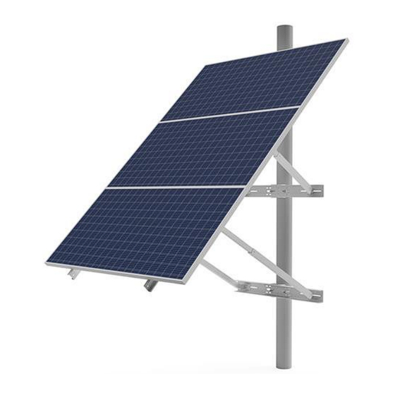
- Page 1 Document # 310135 SunWize Power & Battery Mount Installation Guide Large Format Side of Pole Visit our website: www.sunwizepower.com...
- Page 2 Included Parts: A) 4x 60in Module Rail B) 3x Saddle Bracket C) 2x 26in Tilt Leg Tube D) 4x 24inTilt Leg Strut E) 3x Easy Mount Bracket F) 6x Angle Bracket G) 2x 27in Splice Rail H) 2x 42in Tilt Leg Tube I) 2x 40in Tilt Leg Strut K) 4x 3/8”...
- Page 3 N) 16x ¼” Flange Bolt O) 42x ��/����” Flange Nut M) 42x ��/����” Flange Bolt P) 16x ¼” Flange Nut Q) 1x Anti-Seize Packet...
- Page 4 Rail Length Pipe Size Diameter Max Module Qty. Max Module Qty. (inches) (SCH 40) (Large Format) (Small Format) 240060 6-12in Hardware Note: • Apply anti-seize to all hardware to prevent galling • 1 ft-lb = 12 in-lb = 1.36 Nm •...
- Page 5 Pole Mount Site Preparation • The pole used to support the PV array must be designed per the local soil conditions to meet the following minimum requirements: Array area based at tilted angle Typical sustained wind speed per the recommended local building code. •...
- Page 6 Mount Installation 1. Fasten the upper Easy Mount Solar Bracket to the pole at the desired maximum height of the mount using lag bolts OR use a U-bolt to mount the saddle directly to the pole. DO NOT use the easy mount bracket when using U-bolts.
- Page 7 3. Attach lower Easy Mount Solar Bracket and saddle bracket using same method in steps one and two. Place the top saddle first with “X” spacing, followed by the bottom brackets with “Y” spacing. Mount should face true south (Northern Apply anti-seize Hemisphere) to all hardware.
- Page 8 5. While on the ground, assemble the 121in long module rails. Use qty 2 of the 60.5in rails and the 27.5in rail with qty 4 bolts to create a splice. Ensure the slots for the splice face up on the left arm and down on the right arm.
- Page 9 6. On the ground, lay rails on module holes (but do NOT attach to module) to determine upper angle bracket spacing. Measure between the inside of the module rails. Attach angle brackets so that the module rails can be mounted with the correct spacing. Z “...
- Page 10 7. Attach panel rails to upper saddle L-brackets using 5/16” hardware provided. Apply anti-seize to all hardware. 8. Drop spring nut into tilt leg strut and rotate to lock into place. Slide strut and spring nut into tilt leg tube and adjust to desired length.
- Page 11 9. Attach legs to lower saddle angle brackets. Apply anti-seize to all hardware. 10. Tighten all remaining bolted connections circled below. Tighten using 1/2” wrench to 10-12 ft-lb torque. 11. Check alignment of all assembled parts and ensure all bolted connections are tight.
- Page 12 45 Degree Tilt Position 30 Degree Tilt Position 12. Mount the solar modules to the rails using the 1/4” hardware provided. Apply anti-seize to all hardware.
- Page 13 13. (OPTIONAL) If using the Cable Bracing Accessory Kit, attach one bracket to the lower tilt leg and run the cable to the opposite corner of the saddle bracket. Tighten and lock the cable in place. Repeat with other bracket and cable on opposite side.
Need help?
Do you have a question about the 240060 and is the answer not in the manual?
Questions and answers