Table of Contents
Advertisement
Quick Links
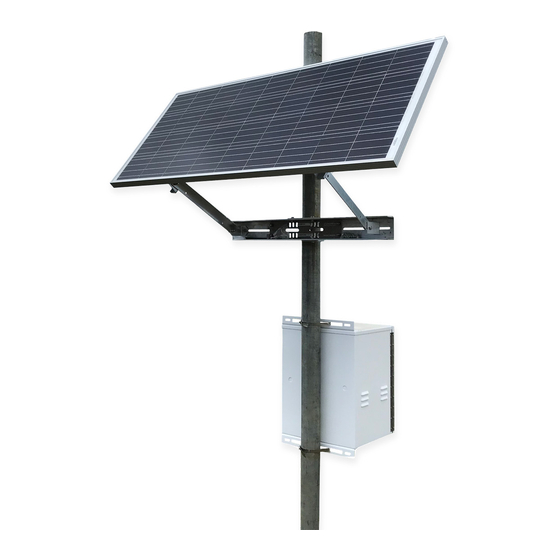
Sunwize Power Ready Express
Quick Start
The purpose of this guide is to assist you in setting up your
system quickly and efficiently.
Share your installation photo:
email to marketing@sunwizepower.com
Important! Prior to field installation
Determine and fill in the information below. Refer to
www.ngdc.noaa.gov/geomag-web/#declination
required information using site Lat./Long. or zip code. See
page 7 for detailed instructions.
Array tilt angle
Magnetic declination
See inside for list of required tools and additional materials.
For technical support call 866-827-6527
Document # 310002
http://
to determine
Advertisement
Table of Contents

Summary of Contents for SunWize Power Ready Express
- Page 1 Document # 310002 Sunwize Power Ready Express Quick Start The purpose of this guide is to assist you in setting up your system quickly and efficiently. Important! Prior to field installation Determine and fill in the information below. Refer to http:// www.ngdc.noaa.gov/geomag-web/#declination...
-
Page 2: System Parts List
System Parts List You will need these tools: PV Modules Wide, medium, and narrow flat head and Phillips screwdrivers PV-Module mount Socket driver set and open end wrenches (3/8” - 3/4”) PV-Module output conductor kit 5/32” Allen Wrench Enclosure 3/16” Allen wrench Enclosure mounting brackets (if required) Magnetic compass Batteries and battery cables... - Page 3 PV Array Installation: Pole Mount Side of Pole Mount Top of Pole Mount Attach top of array structure to pole at desired maximum height using supplied band Attach array with the gimbal to the top of the pole per the manual provided with the mount. clamps or u-bolts per the manual provided with the mount.
- Page 4 PV Array Installation: Ground Mount Ground Mount 1. Turn array to face South. 2. Assemble per the manual provided with the mount. For Reference Only...
-
Page 5: Enclosure Installation
Enclosure Installation Side of Pole Mount Enclosure Ground Mounted Enclosure 1. Mount upper mounting bracket at desired height of enclosure on the pole using U-bolts 1. Install the base mounting pads at the desired location using 1/2 inch concrete fastening or band clamps. -
Page 6: Control Panel Installation
Control Panel Installation Side of Pole Mount Enclosure (Chest Enclosure Same) 1. Remove second set of supplied nuts from mounting studs located on the side wall of the enclosure 2. Adjust first set of nuts on each stud to the same distance from enclosure wall leaving enough stud exposed for control panel and second nuts. 3. -
Page 7: Electrical Installation
Single module with quick connectors Electrical Installation ground wire connects to mounting bolt at module PV Array Wiring with Quick Connectors Set circuit breakers to OFF (open) and remove fuses in enclosure (if provided). 1. Route the output conductors from the PV panel to the enclosure. Secure the conductors to the PV panel frame or the mounting surface using wire ties or other restraining hard- ware (not provided). - Page 8 Electrical Installation PV Array Wiring with Tray Cable Set circuit breakers to OFF (open) and remove fuses in enclosure (if provided). 1. Route the output conductors from the PV panel to the enclosure. Secure the conductors to the PV panel frame or the mounting surface using wire ties or other restraining hard- ware (not provided).
- Page 9 Electrical Installation Battery Wiring For 12V systems Each 12V battery is in parallel with the next. Connect the RED jumper from BAT 1 POSITIVE (+) terminal to the BAT 2 POSITIVE (+) terminal and the BLK jumper from BAT 1 NEGATIVE (-) terminal to the BAT 2 NEGATIVE (-) terminal.
- Page 10 Test the PV System Confirm all connections, fittings, and fasteners are secure and the PV array surface is clean and facing South. Measure Voltages (Confirm all breakers are off before measuring) Set breakers to the ON (closed) position Verify both the PV and battery polarity is positive. If negative, reverse wiring On the charge control panel to the system and check again.
-
Page 11: Connect Your Equipment
Connect Your Equipment 1. Turn the Power Ready System OFF. A. Turn the PV breaker (CB1) OFF B. Turn the Battery breaker (CB2) OFF C. Turn the Load breaker (CB3) OFF D. Connect your equipment to the terminal blocks on the control panel. 2. - Page 12 Calculate Installation Tilt and Azimuth For optimum performance, your PV array should face true south in the Northern Hemisphere (and true north in the Southern Hemisphere). However, when determining direction using a magnetic compass, indicated bearings will vary from true bearings because of the difference between the location of the true and magnetic north poles.
Need help?
Do you have a question about the Power Ready Express and is the answer not in the manual?
Questions and answers