DACE Sectional LUX DC12 Installation & User Manual
Hide thumbs
Also See for Sectional LUX DC12:
- Installation & user manual (12 pages) ,
- Installation & user manual (22 pages)

Related Manuals for DACE Sectional LUX DC12

Summary of Contents for DACE Sectional LUX DC12
- Page 1 Sectional Garage Door Operator 12 Volt DC / 150W ● For Single or Double Sectional Garage Doors ● Proudly manufactured by www.dace.co.za INSTALLATION & USER MANUAL Ver 1.01...
-
Page 2: Table Of Contents
Table of Contents Page Foreword Safety Instruc ons Disclaimer Glossary Technical Specifica ons Parts Iden fica on Assembling and Installing the Operator A aching Manual Release Mechanism to the Trolley Fi ng the Hanger Bracket to the Drive Channel Moun ng the Wall Bracket A aching the Power Head to the Drive Channel Moun ng the Drive Channel A aching the Door Bracket to the Door... -
Page 3: Foreword
FOREWORD Thank you for choosing D.A.C.E. We welcome you to the ever growing interna onal community of DACE product owners. The advanced engineering and high-quality construc on of each DACE product we build is something of which we are proud. -
Page 4: Disclaimer
Addi onally, DACE makes no representa ons or warran es with respect to this manual. This manual may only be copied or distributed as a whole, no altera ons or subsec ons may be distributed or... -
Page 5: Glossary
GLOSSARY This is the small sec on of travel near the end of the door’s closing cycle. If the operator An -Crush Gap receives a trigger in this sec on of travel, the door will always open to prevent possible damage or injury. -
Page 6: Technical Specifica Ons
TECHNICAL SPECIFICATIONS Input Voltage: 220 - 240V AC @50Hz Transformer Voltage Output Voltage: 12 - 18V AC Board Input Supply 12 - 18V AC or 17 - 22V DC Motor Voltage Motor Power (Rated) 150W Maximum Holding Capacity 1200N Maximum Push/Pull Force 50kgF Ba ery 12V DC (5Ah OR 7Ah) -
Page 7: Parts Iden Fica On
PARTS IDENTIFICATION... -
Page 8: Fi Ng The Hanger Bracket To The Drive Channel
ATTACHING MANUAL RELEASE MECHANISM TO THE TROLLEY Using the four Self Tapping 6 x 20mm screws supplied, a ach the Manual Release Mechanism to the Trolley. As these screws are under load when the door is moving or if the door balance spring breaks, it is important that they are screwed in securely. -
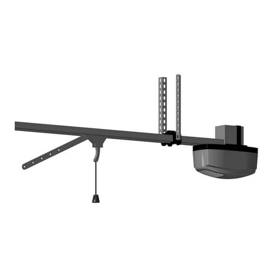
Page 9: A Aching The Power Head To The Drive Channel
ATTACHING THE POWER HEAD TO THE DRIVE CHANNEL A ach the Power Head to the Drive Channel using the U-Brackets and the four M6 x 25mm hex bolts and washers provided. M6 x 25mm Hex Bolts & Washers U-Brackets Drive Channel Power Head MOUNTING THE DRIVE CHANNEL Using the two M6 x 16mm bolts supplied, connect the Drive Channel to the Wall Bracket. -
Page 10: A Aching The Door Bracket To The Door
ATTACHING THE DOOR BRACKET TO THE DOOR With the garage door closed , a ach the Door Bracket to the middle of the door on the side that faces into the garage. To determine the height , align the Door Bracket with the two top door guide rollers. IMPORTANT The Door Bracket is exposed to extreme forces. -
Page 11: Se Ng The Physical Open & Close End Stops
SETTING THE PHYSICAL OPEN & CLOSE END STOPS Se ng the Close Limit: Move the door to the fully closed posi on. Slot the Channel End Stopper into the Drive Channel and ghten in place using the M6 x 16 bolt, ensuring that a gap of 2mm is le between the Channel End Stopper and the Trolley. -
Page 12: Opera Ng The Manual Release Mechanism
OPERATING THE MANUAL RELEASE MECHANISM To re-engage the operator, To disengage the gently pull the Manual operator, gently Release Rope in an upward pull the Manual mo on and then gently Release Rope slide the door in either straight down. direc on un l the Trolley engages. -
Page 13: Programming Menu
▶ An Crush Gap: The An Crush Gap is the 30cm space towards the end of the door closing cycle, before the door is fully closed. This is a built in safety feature to prevent the entrapment of people or animals by the door. The following will happen if the operator receives a trigger from a remote (or the bu ons on the operator) while the door is already in mo on: If the door is closing, the door will stop briefly and then reopen to the fully open posi on. -
Page 14: Se Ng The Open & Close Limits
SETTING THE OPEN & CLOSE LIMITS ..Menu 1 1) Ensure the ba ery is connected to the operator. 2) Press the SET bu on to enter the Programming Menu (Pr). 3) Press the DOWN bu on un l Li is visible. 4) Press the SET bu on. -
Page 15: Se Ng Auto Close
SETTING AUTO CLOSE ..Menu 4 1) Ensure the ba ery is connected to the Operator. 2) Press the SET bu on to enter the Programming Menu (Pr). 3) Press the DOWN bu on un l the Auto Close Menu (AC) is visible. 4) Press the SET bu on to enter the Auto Close Menu. -
Page 16: Enable Or Disable Electric/Magne C Lock
.................Output op ons available (con nued): a) Auxiliary Status (AS): This output indicates the ‘door status’. It can be connected to an external LED to indicate if the door is open or closed and if the ba ery is charging. It can also be connected to a GSM device for remote monitoring. -
Page 17: Programming A Remote Bu On To Turn The Operator Light On & Off
PROGRAMMING A REMOTE BUTTON TO TURN THE OPERATOR LIGHT ON and OFF 1) Ensure the ba ery is connected to the Operator. 2) Press the SET bu on to enter the Programming Menu (Pr). 3) Press the DOWN bu on un l the Remote Menu (rc) is visible. 4) Press the SET bu on to enter the Remote Menu. -
Page 18: Erasing All Remotes And Their Bu Ons From The Operator
ERASING ALL REMOTES and THEIR BUTTONS FROM THE OPERATOR 1) Ensure the ba ery is connected to the Operator. 2) Press the SET bu on to enter the Programming Menu (Pr). 3) Press the DOWN bu on un l the Remote Menu (rc) is visible. 4) Press the SET bu on to enter the Remote Menu. -
Page 19: Control Board Layout
CONTROL BOARD LAYOUT CONTROL BOARD LAYOUT DBUS Marker Input Input Motor Wire (Red) LIMITS: Connect the 4 pin plug from the Drum Mount Operator this is not used on Sec onal or Ver cal Mount Operators Motor Wire REV: (Black/Blue) Connect the 3 pin plug from the motor to the connector. -
Page 20: Safety Beams
Refer to ‘Enable or Disable Electric/Magne c Lock..Menu 6’ for programming. LUX DC12 Control Board Power Input LIMITS AUX LOCK 12V TRIG INF GND Electric Lock DACE Operator Relay Module Ba ery Code: SA001 Magne c Lock DACE External Relay Module... -
Page 21: Auxiliary Status Output
Another example is the switching on of lights or the External deac va on of the home alarm Trigger by triggering a Pulse Stretcher. DACE TRIGGER Relay Module Refer to ‘Se ng Auxiliary Code: SA001 Output..Menu 5’ for programming. -
Page 22: Auxiliary Light
External dedicated bu on, it will remain Light on for a period of 1 hour but can be switched off before 1 hour is DACE up by pressing the same bu on Relay Module again. Code: SA001 Refer to ‘Se ng Auxiliary Output..Menu 5’... - Page 23 ERROR MEANING CAUSE & REMEDY CODE Cause: The infrared beam between the two Safety Beam sensors are blocked, indica ng an obstruc on or the ba eries in the transmi er beam are low. Remedy: Remove anything that may be obstruc ng the doorway. Beams Blocked If there is no obstruc on, check that the Beam’s wiring is correct.
-
Page 24: Warranty
● This warranty is a factory warranty, all goods will be repaired at the factory or one of the DACE designated repair centres. In the case of interna onal customers, the defec ve product must be returned to the supplier from where the product was purchased WITH PROOF OF PURCHASE FROM THAT SUPPLIER.
Need help?
Do you have a question about the Sectional LUX DC12 and is the answer not in the manual?
Questions and answers