Table of Contents
Advertisement
Laguna Tools
X/Series CO2 Laser
Owner's Manual
MX: MCNCLTLCO2MU2012-40W, EX: MCNCLTLCO2EC2436-80W, EX-C: MCNCLTLCO2EC3652-150W
Precision CO2 Laser Engraving & Cutting Machines
EN 2072- Laguna Tools: 744 Refuge Way
Grand Prairie, TX U.S.A. Service: +1 (800) 234-1976
or email: customerservice@lagunatools.com
CO2 Laser Machine © 2021 Laguna Tools 3/01/2021
Advertisement
Table of Contents

Related Manuals for Laguna Tools SmartShop Laser EX-C

Summary of Contents for Laguna Tools SmartShop Laser EX-C
- Page 1 Owner’s Manual MX: MCNCLTLCO2MU2012-40W, EX: MCNCLTLCO2EC2436-80W, EX-C: MCNCLTLCO2EC3652-150W Precision CO2 Laser Engraving & Cutting Machines EN 2072- Laguna Tools: 744 Refuge Way Grand Prairie, TX U.S.A. Service: +1 (800) 234-1976 or email: customerservice@lagunatools.com CO2 Laser Machine © 2021 Laguna Tools 3/01/2021...
-
Page 2: Table Of Contents
Table of Contents- 1.) Machine Briefing. 2.) Setup Preparation & Contents: 2.1.) Preparing For Setup-Receiving, Damage Notifications, Machine Placement, Open Crate (Unboxing). 2.2.) Inventory. 2.3.) Connection Diagrams. 2.4.) Machine Set-Up. 2.5.) Auxiliary Equipment Set-Up Exhaust Ventilation Water Chiller & Pump Air Compressor. 2.6) Software Set-Up &... -
Page 3: Machine Briefing
Machine Briefing: 1.) The machine comes as assembled as possible without impacting shipping costs and the possibility of damage. Because of this, there will always be some setup procedures and adjustments that the craftsman must perform prior to using the machine. Those setup sections that must be done to complete the assembly of the machine are in the Machine Setup sub-section. -
Page 4: Setup Preparation & Contents
Set-Up (Cont’d.): 2.) Setup Preparation & Contents: 2.1.) Preparing For Setup-Receiving, Damage Notifications, Machine Placement, Open Crate (Unboxing). 2.2.) Inventory. 2.3.) Connection Diagrams. 2.4.) Machine Set-Up. 2.5.) Auxiliary Equipment Set-Up Exhaust Ventilation Water Chiller & Pump Air Compressor. 2.6) Software Set-Up & Installation. 2.1.) Preparing For Setup-Receiving. - Page 5 X/Series CO2 Laser Machine Series Damage Notification- 2.1.3) The Machines are thoroughly tested before leaving any or our Laguna Tools Facilities, but that does not mean the Machines would not experience any damage in transit. Before one Signs the Bill of Lading (See Example Below) when the Trucking Company drops off the Machine, visually inspect the entire crate and check for any damage.
- Page 6 Note that on the Bill of Lading as well. 2.1.6.) NOTIFY LAGUNA TOOLS WITHIN 24 HOURS AFTER RECEIVING CRATE WITH SHIPPING or any other type of DAMAGE. We ask customers to notify us within 24 hours of any damage sustained to the packaging and or products. Customers can...
- Page 7 Placement of Machine- 2.1.7.) Placement Prior to removing the machine from the packaging, decide the operating location of the machine. The dimensions and floor space can be found here: Dimensions. • There should be sufficient area at the front of the machine to allow you to work on it comfortably. •...
- Page 8 X/Series CO2 Laser Machine Series Open Crate (Unboxing)- 2.1.8.) Acquire some standard tools for taking apart the Crate. a.) Hammer. b.) Pry Bar. c.) Wire Cutters. d.) Cordless Drill.
- Page 9 2.1.11.) Visually inspect the entire and check for any damage to the crate. We ask customers to NOTIFY LAGUNA TOOLS WITHIN 24 HOURS AFTER RECEIVING NEW X/Series CO2 Laser Machine WITH SHIPPING DAMAGE. Customers can contact us at customerservice@lagunatools.com or call 855-989-9731.
- Page 10 2.2.) Do not unpack the laser tube until prompted in the setup procedures. Again, Per 2.1.3) The Machines are thoroughly tested before leaving any or our Laguna Tools Facilities, but that does not mean the Machines would not experience any damage in transit.
- Page 11 2.2.) Inventory (Cont’d.)- (Cont’d.) Verify the following Items before unpacking items from crate unpacking the MX (MLTX6011) Receiving: • VERY FRAGILE! C02 Glass Laser Tube- • Laser Tube Cover. • Right Side Upper Panel. • Exhaust Tubing. • VERY FRAGILE! C02 Glass Laser Tube.
- Page 12 2.2.) Inventory (Cont’d.)- (Cont’d.) Verify the following Items before unpacking items from crate unpacking the MX (MLTX6011) Receiving: Exhaust Fan- • Laser Tube Cover. • Right Side Upper Panel. • Exhaust Tubing. • VERY FRAGILE! C02 Glass Laser Tube. • Water Chiller. •...
- Page 13 2.3.) Inventory (Cont’d.)- Complete Inventory of Laser Machine 2.3.) After visually inspecting the entire crate and check for any damage to the main components, do a physical inventory of all parts. Here is a Inventory of all Parts utilized to Build Laser Machines and Parts in the Small Parts Box/Toolbox:...
- Page 14 2.3.) Inventory (Cont’d.)- Complete Inventory of Laser Machine Honeycomb Table- Water Tubing (2)-...
- Page 15 2.3.) Inventory (Cont’d.)- Complete Inventory of Laser Machine 10.) Connection Cable (Alarm)- 11.) Exhaust Fan Unit or Blower Unit 9.) Power Cable- 12.) Metal Expanding Exhaust Ducting.
- Page 16 2.4.) Inventory –Toolbox/Small Box of Parts: 13.) & 14.) Ignition Locking Keys 18.) Universal 15.) Thumb Drive 16.) Tools 17.) Air Valve 19.) Spare Limit Switch 20.) Alignment Crosshair Connector...
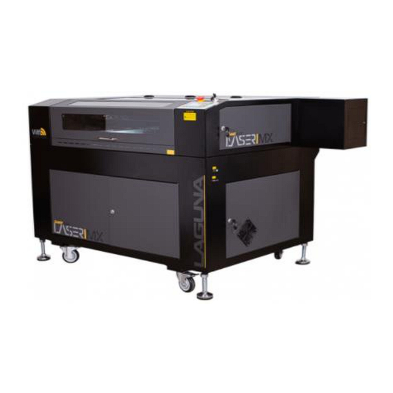
- Page 17 2.3.) Connection Diagrams: Smartshop Laser/MX Series CO2 Laser Machine MX CO2 LASER Fig. 1: Smartshop Laser/MX Series CO2 Laser Machine.
- Page 18 2.3.) Connection Diagrams (cont’d.): Smartshop Laser/EX/EX-C Series CO2 Laser Machine EX CO2 LASER EX-C CO2 LASER Fig. 2: Smartshop Laser/EX/EX-C Series CO2 Laser Machine.
- Page 19 2.4.) Inventory –Toolbox/Small Box of Parts (Cont’d.): 21.) Water Hose Clamps (2)- 22.) Exhaust Hose Clamps- 24.) Air Hose Fitting 25.) Air Hose (Not Supplied)- (Not Supplied)- 23.) Compressor (Not Supplied)-...
- Page 20 2.5.) Machine Set-Up: The following sections should be followed exactly in order to properly set-up the machine. Removing Zip Ties and Shipping Devices- Make sure that the machine is not connected to the power source during laser tube installation. Do not plug in machine or connect anything to a power source until prompted to do so. Use caution when removing zip ties to avoid damaging the belts.
- Page 21 2.5.) Machine Set-Up: Cutting Zip Ties. Inner Laser Machine Chamber-Removing Zip Ties and Shipping Devices: (1) Remove packaging zip ties with scissors or pliers. (2) Remove (2) belt zip ties with scissors or pliers. The machine is shipped such that nothing can move in transit. Use a pair of scissors or pliers to remove all zip ties as described. Avoid using a razor blade or knife when remove the zip ties on belts to avoid damaging the belts.
- Page 22 2.5.) Machine Set-Up (Cont’d.)- Leveling the Machine: Leveling the machine is important to ensure the flatness of the work area and the alignment of the laser mirrors. Make certain to position the laser machine on a flat solid surface and level the machine by adjusting each of the 4 casters.
- Page 23 2.5.) Machine Set-Up (Cont’d.)- Installing Panels and Laser Tube Cover- Installing Panels and Laser Tube Cover Note: This section is similar for all Laguna laser machines. Right Side Upper Panel- These panels are located inside the bottom of the laser machine upon shipment. Remove them and follow the procedure exactly to properly install the panels.
- Page 24 2.6.) Machine Set-Up: Laser Tube Installation- Note: This section is similar for all Laguna Laser Machines. Laser Tube Mounts-...
- Page 25 2.6.) Machine Set-Up: Laser Tube Installation (Cont’d.)- Installing the Laser Tube: ! Please reference the connections diagram when installing. 1.) Unplug the laser machine and all components. ! Avoid electrical shock. 2.) Open the Laser Tube Cover or Rear Panel of the Laser Machine. 3.) Remove the top mounts (E) from each mount by removing the Tube Lock Screws (B).
- Page 26 2.6.) Machine Set-Up: Laser Tube Installation (Cont’d.)- 4.) Carefully place the new, unconnected, laser tube inside the mounts. The Laser Tube is very fragile. 5.) Carefully connect a water tube between the inlet on the rear of the connection panel and the water inlet on the laser tube (left side, cathode side).
- Page 27 2.6.) Machine Set-Up: Laser Tube Installation (Cont’d.)- 6.) Carefully connect a water tube between the outlet on the rear of the connection panel and the water outlet on the laser tube (right side, anode side).
- Page 28 2.6.) Machine Set-Up: Laser Tube Installation (Cont’d.)- 7.) Connect the high voltage (+) terminal (cathode) to the power supply according to the wiring diagram in this manual. Use the wire insulated with the rubber sleeve. ! The connection should be from (+) to (-) the same direction that the laser is firing; towards the first mirror. There is a Liberec small set screw on the end of the cathode terminal.
- Page 29 2.6.) Machine Set-Up: Laser Tube Installation (Cont’d.)- : Ensure the Tube Height Lock Screws (C) are loose. ! If using a level, make sure that the laser machine is on a level surface. Note that it is crucial that the laser tube is parallel to the chassis of the machine.
- Page 30 2.6.) Machine Set-Up: Laser Tube Installation (Cont’d.)- 13.) Do not worry about testing the laser for alignment at this point as we need to install all other systems prior. Water Tubes connect to the "inlet" water port. The Cathode Wire connects to the pin with a set screw. Water Tubes connect to the "outlet"...
- Page 31 2.6.) Machine Set-Up: Laser Tube Installation & Adjustments (Cont’d.)- Focal Lens Adjustments- To make cuts and engravings on different materials, the operator will need to adjust the focal length according to the material’s properties. This is either done using the lift bed and the focal length sensor, or by adjusting manually. A.) Incoming, Unfocused IR Laser Beam B.) Height Adjustment Clamp C.) Focal Lens (Standard is 50.8mm length, 20mm diameter)
- Page 32 2.6.) Machine Set-Up: Laser Tube Installation & Adjustments (Cont’d.)- Installing/Removing Focal Lens Tools Need: N/A 1.) Unscrew the assembly by loosening the (3) head assembly set and remove from the Laser head. You may need to move the Z- axis down for clearance. 2.) Unscrew the lens removal set(4) from (8) nozzle to expose the (7) locking nut.
- Page 33 2.6.) Machine Set-Up: Laser Tube Installation & Adjustments (Cont’d.)-...
- Page 34 2.6.) Machine Set-Up: Laser Tube Installation & Adjustments (Cont’d.)-...
- Page 35 2.6.) Machine Set-Up: Laser Tube Installation & Adjustments (Cont’d.)-...
- Page 36 2.6.) Machine Set-Up: Laser Tube Installation & Adjustments (Cont’d.)- M1 up and down, M2 around, M3 Angle, three screws, through the three screws to determine the Angle of the mirror. When adjusting the optical path, the laser reflection Angle can be changed by adjusting the three screws to realize the purpose of optical path adjustment.
- Page 37 2.6.) Machine Set-Up: Exhaust Ventilation/Fan Blower Operations- Exhaust Ventilation- WARNING! Do not connect to a power supply until the set-up is complete. Do not perform any of the following steps, installations, or adjustments with the machine connected to a power source unless directed to do so. WARNING! The fan can tip over if not fastened to a base.
- Page 38 2.6.) Machine Set-Up: Exhaust Ventilation/Fan Blower Operations- Exhaust Blowing unit for laser machines: (1) Positive Pressure output (air comes out here). (2) Negative pressure input (air is sucked in here). (3) Mounting Bolt Holes. (4) TEFC AC Induction Motor. SKU: N/A included with laser machine Fits: All CO2 and Fiber Laser machines < 100Watt. The purpose of the exhaust blower is to pull harmful gasses away from the machine and operator and direct them to a safe location through the included duct-work.
- Page 39 2.6.) Machine Set-Up: Exhaust Ventilation/Fan Blower Operations- Q: I am not getting enough suction with the included blower to pull the dirty air through a filter arrangement like the in-line filter. A: Because of the higher pressure needed to force air through the filters, the included fan may not be sufficient - if this is the case then attach the filter stack to the output of the exhaust blower.
- Page 40 2.6.) Machine Set-Up: Water Chiller- A Water Chiller must be used to operate the Laser Tube! WARNING! Do not connect to a power supply until the set-up is complete. Do not perform any of the following steps, installations, or adjustments with the machine connected to a power source unless directed to do so.
- Page 41 2.6.) Machine Set-Up: Water Chiller & Pump (Cont’d.)-...
- Page 42 2.6.) Machine Set-Up: Water Chiller Specifications-...
- Page 43 2.6.) Machine Set-Up: Water Chiller & Pump (Cont’d.)-...
- Page 44 2.6.) Machine Set-Up: Water Chiller & Pump (Cont’d.)- The Ruida Controller has several safety features; one of those features detects when water is not in circulation. When this is detected the laser beam is shut off and an alarm sounds until the water can pass through. It is a good idea to test this by pinching the lines of a properly installed chiller.
- Page 45 2.6.) Machine Set-Up: Air Compressor (Air Pump)- ! Do not connect to a power supply until the set-up is complete. Do not perform any of the following steps, installations, or adjustments with the machine connected to a power source unless directed to do so. : Make sure the air hose fits all the way into the adapter.
- Page 46 2.6.) Machine Set-Up: Air Compressor (Air Pump) Cont’d.- The Air Compressor supplies a continuous air supply through the laser head assembly so that fumes and debris cannot obstruct the laser pathway. The air compressor must be used in operation with the CO2 Laser machine. Q: Can I use a different air compressor than the one included? A: The unit was chosen because it is best suited for the operating conditions of the Laser Machine.
- Page 47 2.6.) Machine Set-Up: Software Set-Up & Installation- To configure the included Software, please refer to the Software Owner’s Manual: Laser Engraving & Cutting Software User Manual-RDWorks V8.0 & Lightburn: Software available @ http//: RDWorks 8.0 Download (Free) - RDWorks.exe (informer.com) Software available @ https://lightburnsoftware.com...
-
Page 48: Reference Information
3.) Reference Information- LAGUNA LASER - Precision Cutting & Engraving CO2 laser machines function by essentially bouncing light emissions between mirrors until the beam is strong enough to penetrate a partially transparent mirror at the tip of the router head. These lasers are capable of cutting most polymeric and composite materials. - Page 49 3.) Reference Information (Cont’d.)- CO2 Laser Dimensional Specifications-...
- Page 50 3.) Reference Information (Cont’d.)- CO2 Laser Dimensional Specifications-...
- Page 51 3.) Reference Information (Cont’d.)- CO2 Laser Dimensional Specifications-...
- Page 52 3.) Reference Information (Cont’d.)- Ammeter On & Off Switch E-Stop: Make ¼ Turn Clockwise to disengage E-Stop Ruida Control Panel Smartshop MX/EX/EX-C Laser AMMETER/Machine E-Stop & On/Off Switch...
- Page 53 3.) Reference Information (Cont’d.)- Ruida Control Panel Ruida Control Panel...
- Page 54 3.) Reference Information (Cont’d.)- Ruida Control Panel Running Progress Bar Running Status Net Status Working Number File Dimension...
- Page 55 3.) Reference Information: Dimensions- Smartshop EX Smartshop MX Smartshop EX-C...
- Page 56 3.) Reference Information: Laser Machine Capacities and Effective Volume- Smartshop EX-(Example)
-
Page 57: Accessories
The following accessories are designed for the X-Series CO2 Laser Machines. These instructions should be followed exactly to properly set up the equipment. Some of these accessories are designed to fit multiple machines offered by Laguna Tools. Fume Extraction Machine: Features •Models: 3HP –... - Page 58 Q: How do I use the in-line model? A: Each laser machine that Laguna Tools sells comes with an auxiliary blower. If the machine does not have a fume extractor, the blower is used to move the fumes to a location away from the machine and operators. With a filter stack (in line model) the...
- Page 59 4.) Accessories- Accessories & Options- SKU: N/A Categories: 4th Axis Turners, CNC Attachments, CNC Parts & Accessories Description: • The 3 Jaw Rotary Attachment goes on Laguna Lasers to allow 4th axis laser engraving and cutting. Start engraving cups, bottles, and anything you can turn! •...
- Page 60 4.) Accessories- Accessories & Options- Honeycomb Table SKU: N/A included with Laser Machine. Fits: All CO2 and Fiber Laser Machines, depending on work area. Our Honeycomb tables are great for mounting and positioning work pieces. These tables allow for repeated use without damage and allow the debris to fall through and not interfere with the laser process.
-
Page 61: Maintenance
5.) Maintenance- Service Schedule Many laser engraving/cutting machines are sold under a service contract - a document outlining servicing tasks that must be completed and verified on a regular basis. These machines are not under a binding contract but it is in the owner's best interest to follow this schedule as closely as possible. - Page 62 Replacement Parts - Many of the replacement parts can be purchased from several different sources. There are no components in the machine that are proprietary to Laguna Tools - making it easier for the service technician to find replacement parts like belts, motors, mirrors, mounts, and electronics.
- Page 63 5.) Maintenance- If Mirrors are Dirty - Check the exhaust system connections and CFM requirement of the machine. Often the mirrors are contaminated by fumes or particulate matter in circulation around the work area. It is the exhaust systems primary function to direct these contaminants away from sensitive components like the mirrors.
- Page 64 6.) Troubleshooting (Cont’d.)- Q: How often do I need to change the Laser Tube? A: The Laser Tube is classified as a consumable part and has a rated lifespan of 5000 hours of use. However, several variables affect the lifespan of the laser tube, like the power setting used and the quality of water coolant used. NOTICE: Only Deionized or Distilled Water should be used with the Chiller/Laser Tube Cooling System.
- Page 65 6.) Troubleshooting (Cont’d.)- Q: What type of lubricant should I use for the linear bearings? A: White lithium (PTFE) grease is recommended. Q: Do I need to use a Fume Extractor with a CO2 laser cutting machine? A: You must vent the machine to a safe location that will not harm yourself as the operator or any bystanders. This is most easily done with the use of a fume extractor machine.
-
Page 66: Material Laser Parameters
7.) Material Laser Parameters- Use the following tables and select the material closest in material properties to the workpiece to be cut or engraved. - Page 67 7.) Material Laser Parameters (Cont’d.)-...
- Page 68 8.) Wiring-...
- Page 69 8.) Wiring (Cont’d.)-...
- Page 70 Customer Service and include the (RMA) number with any and all returned parts/components requesting warranty coverage.* Any machines returned to Laguna Tools must be returned with packaging in the same manner in which it was received. If a part or blade is being returned it must have adequate packaging to ensure no damage is received during shipping.
- Page 71 Laguna Tools Customer Support Website. The labor required to install replacement parts is the responsibility of the user. Laguna Tools is not responsible for damage or loss caused by a freight company or other circumstances not in our control. All claims for loss or damaged goods must be notified to Laguna Tools within twenty-four hours of delivery.
- Page 72 9.) Laguna Tools Warranty-...
- Page 73 Parts, under warranty, are shipped at Laguna Tools, Inc.’s cost either by common carrier, FEDEX ground service or a similar method. Technical support to install replacement parts is primarily provided by phone, fax, e-mail or Laguna Tools Customer Support Website.
- Page 74 Dealer Machinery Warranty **Any machines returned to Laguna Tools must be returned with packaging in the same manner in which it was received. If a part or blade is being returned it must have adequate packaging to ensure no damage is received during shipping.
- Page 75 9.) Laguna Tools Packaging/Laguna Tools RMA Example- RMA #...
- Page 76 9.) Laguna Tools Packaging/Laguna Tools BILL of LADING Example-...
Need help?
Do you have a question about the SmartShop Laser EX-C and is the answer not in the manual?
Questions and answers