Table of Contents
Advertisement
Quick Links
Portable Air Conditioner
User Manual
MODEL:
PAG-S05KCO610C
PAG-S06KCO630C
Thank you for selecting our quality appliance.
Please be sure to read this user manual carefully before using.
Any question, please contact the professional service for help.
IMPORTANT: The remote control and hardware necessary to use your
new product is included inside the box. You will find them inserted in
the Styrofoam included in the box.
Advertisement
Table of Contents

Related Manuals for Global Commander PAG-S05KCO610C

Summary of Contents for Global Commander PAG-S05KCO610C
- Page 1 Portable Air Conditioner User Manual MODEL: PAG-S05KCO610C PAG-S06KCO630C Thank you for selecting our quality appliance. Please be sure to read this user manual carefully before using. Any question, please contact the professional service for help. IMPORTANT: The remote control and hardware necessary to use your new product is included inside the box.
-
Page 2: Table Of Contents
CONTENTS IMPORTANT SAFEGUARDS DESCRIPTION INSTALLATION INSTRUCTIONS DESCRIPTION OF THE DISPLAY SCREEN REMOTE CONTROL MANUAL TIPS FOR CORRECT USE WATER DRAINAGE METHOD CLEANING START-END OF SEASON OPERATIONS TROUBLESHOOTING ASSISTANCE... -
Page 3: Important Safeguards
IMPORTANT SAFEGUARDS IMPORTANT SAFEGUARDS ● This appliance is for household use only. ● Disconnect the appliance from its power source during service and when replacing parts and cleaning. ● Please note: Check the nameplate for the type of refrigerant gas used in your appliance. - Page 4 IMPORTANT SAFEGUARDS ● Do not clean the unit with water. Water can enter the unit and damage the insulation, creating a shock hazard. If water enters the unit, unplug it immediately and contact Customer Service. ● Utilize two or more people to lift and install the unit. ●...
- Page 5 IMPORTANT SAFEGUARDS Ventilated area (open doors and Windows) 11. Ensure that the working area is open or well ventilated before turning on the system or performing hot work. Ventilation should be maintained during operation. Ventilation quickly displaces safely diluted leaked refrigerant into the atmosphere. 12.
- Page 6 IMPORTANT SAFEGUARDS 1. Master the skills and knowledge of basic safety welding and safety protection level of combustible refrigerant. 2. Familiar with product Develop, Combustible refrigerant system (The development process and design and design personnel, supervision enterprise capable of design. test personnel personnel.
- Page 7 IMPORTANT SAFEGUARDS Fire extinguisher Carry a fire extinguisher during installation and maintenance. There should be at least two kinds of dry powder, carbon dioxide and foam extinguishers in the maintenance site, and they should be placed in the prescribed position with eye-catching signs and accessible places.
- Page 8 IMPORTANT SAFEGUARDS NOTE: The use of silicon sealant may inhibit the effectiveness of some types of leak detection equipment. Intrinsically safe components do not have to be isolated prior to working on them. REPAIR TO INTRINSICALLY SAFE COMPONENTS ● Do not apply any permanent inductive or capacitance loads to the circuit without ensuring that this will not exceed the permissible voltage and current permitted for the equipment in use.
- Page 9 IMPORTANT SAFEGUARDS ● Label the system when charging is complete (if not already). ● Extreme care shall be taken not to overfill the refrigeration system. Prior to recharging the system it shall be pressure tested with OFN. The system shall be leak tested on completion of charging but prior to commissioning.
- Page 10 IMPORTANT SAFEGUARDS RECOVERY When removing refrigerant from a system, either for servicing or decommissioning, it is recommended good practice that all refrigerants are removed safely. When transferring refrigerant into cylinders, ensure that only appropriate refrigerant recovery cylinders are employed. Ensure that the correct number of cylinders for holding the total system charge are available.All cylinders to be used are designated for the recovered refrigerant and labelled for that refrigerant (i.e.
- Page 11 IMPORTANT SAFEGUARDS 1.4 Checking for presence of refrigerant The area shall be checked with an appropriate refrigerant detector prior to and during work, to ensure the technician is aware of potentially flammable atmospheres. Ensure that the leak tection equipment being used is suitable for use with flammable refrigerants, i.e.
- Page 12 IMPORTANT SAFEGUARDS 1.9 Checks to electrical devices Repair and maintenance to electrical components shall include initial safety checks and component inspection procedures. If a fault exists that could compromise safety, then no electrical supply shall be connected to the circuit until it is satisfactorily dealt with.
- Page 13 IMPORTANT SAFEGUARDS According the US and CANDA ruler: CAN ICES-003 (B)/NMB-003(B) FCC Caution This device complies with part 15 of the FCC Rules. Operation is subject to the following two conditions: (1) This device may not cause harmful interference, and (2) this device must accept any interference received, including interference that may cause undesired operation.
-
Page 14: Description
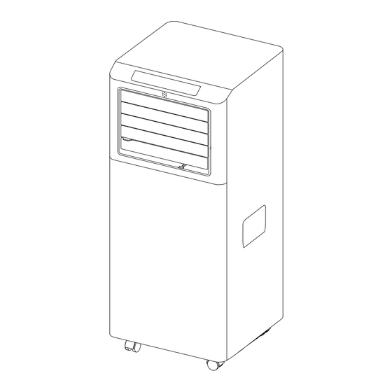
DESCRIPTION 1. Control panel 2. Remote control receiver 3. Deflector 4. Handle (both sides) 5. Castors 6. Intake grille 7. Air outlet grille 8. Intake grille 9. Plug fixer 10. Condenser drain 11. Power cable *Open the deflector before use the appliance. ACCESSORIES QUANTITY PARTS... -
Page 15: Installation Instructions
INSTALLATION INSTRUCTIONS EXHAUSTING HOT AIR In the Cool Mode the appliance must be placed close to a window or opening so that the warm exhaust air can be ducted outside. First position unit on a flat floor and make sure there’s a minimum of 18”... - Page 16 INSTALLATION INSTRUCTIONS Window slider Window slider WINDOW SLIDER KIT INSTALLATION 1: Parts: A) Panel B) Panel with one hole C) Screw to lock window kit in place 2: Assembly: Slide Panel B into Panel A and size to widow width. Windows sizes vary. When sizing the window width, be sure that the window kit assembly is free from gaps from gaps and/or air pockets when taking measurements.
- Page 17 INSTALLATION INSTRUCTIONS 1. Cut the foam seal(adhesive type) to the proper length and attach it to the window sash. 2. Attach the window slider kit to the window sash. Adjust the length of the window slider kit according to the width of window. If necessary, mark the kit and cut one end down to properly fit the window.
- Page 18 INSTALLATION INSTRUCTIONS LOCATION ● The unit should be placed on a firm foundation to minimize noise and vibration. For safe and secure positioning. place the unit on a smooth, level floor strong enough to support the unit. ● The unit has casters to aid placement, but it should only be rolled on smooth, flat surfaces.
-
Page 19: Description Of The Display Screen
DESCRIPTION OF THE DISPLAY SCREEN The control panel is on the top of the appliance, enables you to manage part functions without remote controller, but to fully exploit its potential, you must use the remote controller. 1.Timer button A .Cool symbol 2.Fan button B.Dehumidify symbol 3.Increase button... - Page 20 DESCRIPTION OF THE DISPLAY SCREEN The most suitable temperature for the room during the summer varies from 24°C to 27°C (75°F to 81°F). You are recommended, however, not to set a temperature much below the outdoor temperature. The fan speed difference is more noticeable when the appliance is under Fan mode but may not be noticeable under Cool mode.
- Page 21 DESCRIPTION OF THE DISPLAY SCREEN SETTING THE TIMER ● This timer can be used to delay the appliance start-up or shutdown, this avoids wasting electricity by optimizing operating periods. * Programming start-up ● Turn on the appliance, choose the mode you want, for example Dehumidify mode, high fan speed.
- Page 22 DESCRIPTION OF THE DISPLAY SCREEN SELF-DIAGNOSIS The appliance has a self-diagnosis system to identify a number of malfunctions. Error messages are displayed on the appliance display. IF IS DISPLAYED WHAT SHOULD I DO? If this is displayed, contact your local authorize service center. PROBE FAILURE (sensor damaged) Empty the internal safety tank,...
-
Page 23: Remote Control Manual
REMOTE CONTROL MANUAL On/Off button Fan speed button Increase button Mode button Decrease button Swing button Timer button Sleep button Unit Switch button √ Point the remote control at the sensor on the appliance. √ The remote control must be no more than 23ft (7 meters) away from the appliance (without obstacles between the remote control and the receiver). - Page 24 REMOTE CONTROL MANUAL INSERTING OR REPLACING THE BATTERIES ● Remove the cover on the rear of the remote control. ● Insert two "AAA" 1.5V batteries in the correct position (see instructions inside the battery compartment). NOTE: √ If the remote control unit is replaced or disposed of, the batteries must be removed and discarded in accordance with current legislation as they are harmful to the environment.
- Page 25 REMOTE CONTROL MANUAL FAN mode When using the appliance in this mode, the air hose does not need to be attached. ● Press the “ ” button a number of times until the “ ” symbol appears. ● Select the required fan speed by pressing the “ ”...
- Page 26 REMOTE CONTROL MANUAL SLEEP FUNCTION This function is useful for the night as it gradually reduces operation of the appliance. To set this function correctly: ● Select the cool or heat mode as described above. ● Press the button. The appliance operates in the previously selected mode. When you choose the sleep function, the screen will reduce the brightness, and the fan speed is low.
-
Page 27: Tips For Correct Use
REMOTE CONTROL MANUAL Switch from Celsius to Fahrenheit When the appliance is running, press the “ ” button, then you can change the unit of temperature. For example: Before change, in cool mode, the screen display like fig1. After change, in cool mode, the screen display like fig2. Fig.1 Fig. -
Page 28: Water Drainage Method
WATER DRAINAGE METHOD When there is excess water condensation inside the unit, the appliance stops running and shows “ ” (FULL TANK as mentioned in SELF-DIAGNOSIE). This indicates that the water condensation needs to be drained using the following procedures: Manual Draining (fig.14) Water may need to be drained in high humidity areas 1. -
Page 29: Cleaning
CLEANING Before cleaning or maintenance, turn the appliance off by pressing the button on the control panel or remote control, wait for a few minutes then unplug from the mains socket. CLEANING THE CABINET You should clean the appliance with a slightly damp cloth then dry with a dry cloth. ●... -
Page 30: Start-End Of Season Operations
START-END OF SEASON OPERATIONS START OF SEASON CHECKS Make sure the power cable and plug are undamaged and the earth system is efficient. Follow the installation instructions precisely. END OF SEASON OPERATIONS To empty the internal circuit completely of water, remove the cap. Run off all water left into a basin. -
Page 31: Troubleshooting
TROUBLESHOOTING PROBLEM CAUSE SOLUTION The appliance ● There is no current ● Wait does not come on ● It is not plugged into the mains ● Plug into the mains ● ● The internal safety device has Wait 30 minutes, if the problem tripped persists, contact your service center... -
Page 32: Assistance
ASSISTANCE Distributed by Ouellet Canada Inc. 1 877 247-3461 Before returning the unit to the retailer, for any problem related to the installation, use or proper functioning of the unit; contact our customer support department. One of our agents will guide you through the next steps.
Need help?
Do you have a question about the PAG-S05KCO610C and is the answer not in the manual?
Questions and answers