Advertisement
Quick Links
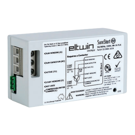
SureStart® 115/230V
Instruction Guide
SSxB Series
/ Single Phase
Parts List:
1 x SureStart Soft starter
1 x Red Lead
1 x Blue Wire
1 x Black Wire
SureStart® 115/230V HVAC installation – SSxB Series:
This model SureStart® functions only as a soft starter, a contactor is still required. This model can be suitable for a wide range of applications. Some
degree of care is needed to determine the correct wiring.
Caution& Warning:
1
All voltage to equipment MUST be disconnected before removing any devices.
2
Allow 2 minutes to discharge run capacitor before disconnecting.
3
Do not swap the Run & Start Windings.
4
Prior to installation, be sure all start capacitors & start relays, along with hard-starters and/or any other start-assist devices, are removed.
5
The start capacitor is built into the soft starter.
6
Loose terminals can lead to heating & subsequent damage to the soft starter. As per, UL508 standard, ensure below tightening torques.
7
OPENING OF THE SOFT STARTER UNIT WILL VOID THE WARRANTY!
LED Flash Codes:
Flash Code
Rapid Flash (10 / 1 sec)
Triple Flash (3 / 3 secs)
Slow Flash (1 / 3 secs)
Steady Flash (1 / 1 sec)
[NOTE: LED fault indicator remains off in normal running mode.]
Field Wiring Specifications:
Wire Range: 8 to 12 AWG Cu, stranded, for terminals (Run Winding (R) and Active(T2))
12 to 16 AWG Cu, stranded, for terminals (Run Capacitor (RC), Start Winding (S), and Compressor/Motor Common (C), these are supplied)
Tightening Torque:
11.5 LBS-IN LARGE TERMINALS, 4.5LBS-IN SMALL TERMINALS.
Field wiring conductors shall be rated 167°F [75°C]
Minimum end use enclosure size: 10" x 8" x 6"
• CRIMP CORRECT SIZED FERRULES TO ENSURE PROPER TERMINATION
• INSERTION LENGTH OF FERRULE "D": 11 ± 1 MM (0.43 ±0.04")
• CABLE BEND RADIUS "R" > 38MM (1.5") MINIMUM
Sample Wiring Schematic
SC
L
T
Field
Contactor
Supply
1P/2P
* ST Start Thermistor
* SR Start Relay
* SC Start Capacitor
Note: If installed, remove all of the above
devices(May be factory installed)
Eltwin Group
sales@eltwin-hyper.com
eltwin-hyper.com
Technical Contact: techsupport@eltwin-hyper.com
1 x Brown Wire
1 x Mounting Bracket
1 x Green Connector
1 x Pack of two Ferrules
Lockout on 3 failed starts
Lockout on overcurrent
SR
Start
H
C
To Fan
F
Run
S
Capacito r
Compressor
Run
R
C
Common
Definition
Low Voltage
Cycle delay / Faults
SureStart
Installation
C C
L
T
Run
C
Co
o
o
n
n
a t
a t
t c
t c
r r o
Field
1
p/
/
2
p p
Capacitor
Supply
Common
Instruction Guide
Time to re-start attempt
3 min
50 min
10 min
3 min
(Color May Vary)
Run Winding(R )
Run Capacitor( RC)
Active( T2)
Start Winding( S)
H H
Start
Not Used
ToFan
Compressor Common (C)
F F
S S
Compressor
Compressor
Run
R R
C C
1/2
Advertisement

Related Manuals for eltwin SureStart SS B Series

Summary of Contents for eltwin SureStart SS B Series
- Page 1 Supply 1P/2P Capacitor Supply Compressor Compressor Compressor * ST Start Thermistor * SR Start Relay * SC Start Capacitor Common Common Note: If installed, remove all of the above devices(May be factory installed) Eltwin Group sales@eltwin-hyper.com eltwin-hyper.com Technical Contact: techsupport@eltwin-hyper.com...
- Page 2 Eltwin North America Eltwin Hyper 1390 Gateway Drive 3/243 Shellharbour Rd Elgin, IL 60124...
Need help?
Do you have a question about the SureStart SS B Series and is the answer not in the manual?
Questions and answers