ASROCK ALIVENF7G-HD720P User Manual
Hide thumbs
Also See for ALIVENF7G-HD720P:
- Installation manual (232 pages) ,
- User manual (56 pages) ,
- User manual (56 pages)
Advertisement
Quick Links
Copyright Notice:
Copyright Notice:
Copyright Notice:
Copyright Notice:
Copyright Notice:
No part of this installation guide may be reproduced, transcribed, transmitted, or trans-
lated in any language, in any form or by any means, except duplication of documen-
tation by the purchaser for backup purpose, without written consent of ASRock Inc.
Products and corporate names appearing in this guide may or may not be registered
trademarks or copyrights of their respective companies, and are used only for identifica-
tion or explanation and to the owners' benefit, without intent to infringe.
Disclaimer:
Disclaimer:
Disclaimer:
Disclaimer:
Disclaimer:
Specifications and information contained in this guide are furnished for informational
use only and subject to change without notice, and should not be constructed as a
commitment by ASRock. ASRock assumes no responsibility for any errors or omissions
that may appear in this guide.
With respect to the contents of this guide, ASRock does not provide warranty of any kind,
either expressed or implied, including but not limited to the implied warranties or
conditions of merchantability or fitness for a particular purpose. In no event shall
ASRock, its directors, officers, employees, or agents be liable for any indirect, special,
incidental, or consequential damages (including damages for loss of profits, loss of
business, loss of data, interruption of business and the like), even if ASRock has been
advised of the possibility of such damages arising from any defect or error in the guide
or product.
This device complies with Part 15 of the FCC Rules. Operation is subject to the
following two conditions:
(1) this device may not cause harmful interference, and
(2) this device must accept any interference received, including interference that
may cause undesired operation.
CALIFORNIA, USA ONLY
The Lithium battery adopted on this motherboard contains Perchlorate, a toxic
substance controlled in Perchlorate Best Management Practices (BMP) regulations
passed by the California Legislature. When you discard the Lithium battery in
California, USA, please follow the related regulations in advance.
"Perchlorate Material-special handling may apply, see
www.dtsc.ca.gov/hazardouswaste/perchlorate"
ASRock Website: http://www.asrock.com
Copyright©2007 ASRock INC. All rights reserved.
ASRock
Published July 2007
ALiveNF7G-HD720p
Motherboard
1 1 1 1 1
Advertisement

Related Manuals for ASROCK ALIVENF7G-HD720P


Summary of Contents for ASROCK ALIVENF7G-HD720P
- Page 1 ASRock. ASRock assumes no responsibility for any errors or omissions that may appear in this guide. With respect to the contents of this guide, ASRock does not provide warranty of any kind, either expressed or implied, including but not limited to the implied warranties or conditions of merchantability or fitness for a particular purpose.
-
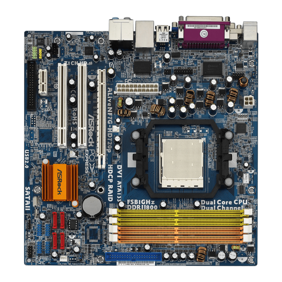
Page 2: Motherboard Layout
Chassis Speaker Header (SPEAKER 1) CPU Fan Connector (CPU_FAN1) Third SATAII Connector (SATAII_3 (PORT2)) 2 x 240-pin DDRII DIMM Slots NVIDIA GeForce 7050 / nForce 630A MCP (Dual Channel A: DDRII_1, DDRII_2; Yellow) PCI Express x1 Slot (PCIE2) 2 x 240-pin DDRII DIMM Slots Floppy Connector (FLOPPY1) (Dual Channel B: DDRII_3, DDRII_4;... - Page 3 (No. 5) (No. 6) (No. 4) To enable Multi-Streaming function, you need to connect a front panel audio cable to the front panel audio header. After restarting your computer, you will find “Mixer” tool on your system. Please select “Mixer ToolBox”...
- Page 4 This Quick Installation Guide contains introduction of the motherboard and step-by- step installation guide. More detailed information of the motherboard can be found in the user manual presented in the Support CD. Because the motherboard specifications and the BIOS software might be updated, the content of this manual will be subject to change without notice.
- Page 5 Specifications Specifications Specifications Specifications Specifications Platform - Micro ATX Form Factor: 9.6-in x 9.6-in, 24.4 cm x 24.4 cm - Socket AM2 for AMD Athlon 64FX / 64X2 / X2 / 64 and Sempron processors - AMD LIVE! Ready - Supports AMD’s Cool ‘n’ Quiet Technology - FSB 1000 MHz (2.0 GT/s)
- Page 6 Line in/Front Speaker/Microphone (see CAUTION 9) Connector - 4 x Serial ATAII 3.0Gb/s connectors, support RAID (RAID 0, RAID 1, RAID 0+1, RAID 5, JBOD), NCQ, AHCI and “Hot Plug” functions (see CAUTION 10) - 1 x ATA133 IDE connector (supports 2 x IDE devices)
- Page 7 Overclocking may affect your system stability, or even cause damage to the components and devices of your system. It should be done at your own risk and expense. We are not responsible for possible damage caused by overclocking.
- Page 8 12. Microsoft Windows Vista / Vista 64-bit driver keeps on updating now. As long as we have the latest driver, we will update it to our website in the future. Please visit our website for Microsoft ® Windows ® Vista...
- Page 9 Windows Vista * If you need to use CyberLink PowerDVD Ultra version 7.2 or 7.3, we suggest to disable Hardware Acceleration function for better playback performance and compatibility. After executing CyberLink PowerDVD Ultra program, please follow below steps to disable Hardware Acceleration function.
- Page 10 NEW ORLEANS CONCERT MPEG-2 ONE SIX RIGHT MPEG-2 TERWILLIGER * MPEG-4-AVC mentioned above refers to the same format of H.264. * Above passed films are tested under below configuration. Items Configurations AMD Athlon 64X2 5200+ Onboard VGA with DVI-D port...
- Page 11 Installation Installation Installation This is a Micro ATX form factor (9.6-in x 9.6-in, 24.4 cm x 24.4 cm) motherboard. Before you install the motherboard, study the configuration of your chassis to en- sure that the motherboard fits into it. Pre-installation Precautions...
-
Page 12: Installation Of Cpu Fan And Heatsink
Step 4. When the CPU is in place, press it firmly on the socket while you push down the socket lever to secure the CPU. The lever clicks on the side tab to indicate that it is locked. - Page 13 (the same brand, speed, size and chip- type) DDRII DIMM pair in the slots of the same color. In other words, you have to install identical DDRII DIMM pair in Dual Channel A (DDRII_1 and DDRII_2;...
- Page 14 Unlock a DIMM slot by pressing the retaining clips outward. Step 2. Align a DIMM on the slot such that the notch on the DIMM matches the break on the slot. The DIMM only fits in one correct orientation. It will cause permanent damage to the motherboard and the DIMM if you force the DIMM into the slot at incorrect orientation.
- Page 15 2.4 Expansion Slots (PCI and PCI Express Slots) There are 2 PCI slots and 2 PCI Express slots on this motherboard. PCI slots: PCI slots are used to install expansion cards that have the 32-bit PCI interface. PCIE Slots: PCIE1 (PCIE x16 slot) is used for PCI Express cards with x16 lane width graphics cards.
- Page 16 To enable dual monitor feature, please follow the below steps: 1. Connect the DVI-D monitor cable to the VGA/DVI-D port on the I/O panel of this motherboard. Connect the D-Sub monitor cable to the VGA/D-Sub port on the I/O panel of this motherboard.
- Page 17 PCI Express VGA card to PCI Express slot. Please refer to page 15 for proper expansion card installation procedures for details. 2. Connect the DVI-D monitor cable to the VGA/DVI-D port on the I/O panel of this motherboard. Connect the D-Sub monitor cable to the VGA/D-Sub port on the I/O panel of this motherboard.
- Page 18 - such as a computer, DVD player or set-top box - and the digital display, or receiver - such as a monitor, television or projector. In other words, HDCP specification is designed to protect the integrity of content as it is being transmitted.
- Page 19 The DVI-D port for the chipset adopted on this motherboard can support DVI/HDCP and HDMI format signal. You may use the DVI to HDMI adapter to convert the DVI-D port to HDMI interface. Please follow below steps to enable HDMI audio function according to the OS you install.
- Page 20 CLRCMOS1 for 5 seconds. However, please do not clear the CMOS right after you update the BIOS. If you need to clear the CMOS when you just finish updating the BIOS, you must boot up the system first, and then shut it down before you do the clear-CMOS action.
-
Page 21: Onboard Headers/Connectors
Floppy Connector (33-pin FLOPPY1) (see p.2 No. 26) the red-striped side to Pin1 Note: Make sure the red-striped side of the cable is plugged into Pin1 side of the connector. Primary IDE connector (Blue) (39-pin IDE1, see p.2 No. 10) - Page 22 USB 2.0 Headers Besides four default USB 2.0 ports on the I/O panel, there are (9-pin USB10_11) four USB 2.0 headers on this (see p.2 No. 17) motherboard. Each USB 2.0 header can support two USB 2.0 ports. (9-pin USB8_9) (see p.2 No.
- Page 23 HDA to function correctly. Please follow the instruction in our manual and chassis manual to install your system. 2. If you use AC’97 audio panel, please install it to the front panel audio header as below: A. Connect Mic_IN (MIC) to MIC2_L.
- Page 24 Though this motherboard provides 4-Pin CPU fan (Quiet Fan) support, the 3-Pin CPU fan still can work successfully even without the fan speed control function. If you plan to connect the 3-Pin CPU fan to the CPU fan connector on this motherboard, please connect it to Pin 1-3.
- Page 25 HDMI_SPDIF Header HDMI_SPDIF header, providing SPDIF audio output to HDMI VGA (3-pin HDMI_SPDIF1) card, allows the system to (see p.2 No. 28) connect HDMI Digital TV/ projector/LCD devices. Please connect the HDMI_SPDIF connector of HDMI VGA card to this header.
- Page 26 HDMI (High-Definition Multi-media Interface) is an all-digital audio/video specification, which provides an interface between any compatible digital audio/video source, such as a set-top box, DVD player, A/V receiver and a compatible digital audio or video monitor, such as a digital television (DTV). A complete HDMI system requires a HDMI VGA card and a HDMI ready motherboard with a HDMI_SPDIF header.
- Page 27 Before installing SATAII hard disk to your computer, please carefully read below SATAII hard disk setup guide. Some default setting of SATAII hard disks may not be at SATAII mode, which operate with the best performance. In order to enable SATAII function, please follow the below instruction with different vendors to correctly adjust your SATAII hard disk to SATAII mode in advance;...
- Page 28 STEP 2: Connect the SATA power cable to the SATA / SATAII hard disk. STEP 3: Connect one end of the SATA data cable to the motherboard’s SATAII connector. STEP 4: Connect the other end of the SATA data cable to the SATA / SATAII hard disk. 2.12 2.12...
- Page 29 Before installing Windows 2000 to your system, your Windows 2000optical disk is supposed to include SP4. If there is no SP4 included in your disk, please visit the below website for proper procedures of making a SP4 disk: http://www.microsoft.com/Windows2000/downloads/servicepacks/sp4/spdeploy. htm#the_integrated_installation_fmay 2.14.1 Installing Windows...
- Page 30 Press any key to continue Please insert a floppy diskette into the floppy drive. Select your required item on the list according to the mode you choose and the OS you install. Then press any key. The system will start to format the floppy diskette and copy SATA / SATAII drivers into the floppy diskette.
-
Page 31: Installing Windows
64-bit OS on your system. When you see “Where do you want to install Windows?” page, please insert the ASRock Support CD into your optical drive, and click the “Load Driver” button on the left on the bottom to load the NVIDIA ®... - Page 32 ® 2000 to your system, your Windows ® 2000optical disk is supposed to include SP4. If there is no SP4 included in your disk, please visit the below website for proper procedures of making a SP4 disk: http://www.microsoft.com/Windows2000/downloads/servicepacks/sp4/spdeploy. htm#the_integrated_installation_fmay 2.15.1 Installing Windows 2.15.1 Installing Windows...
-
Page 33: Untied Overclocking Technology
(create, convert, delete, or rebuild) RAID functions on SATA / SATAII HDDs, you still need to set up “SATA Operation Mode” to [RAID] in BIOS first. Then, please set the RAID configuration by using the Windows RAID installation guide in the following path in the Support CD: .. - Page 34 CD-ROM drive. It will display the Main Menu automatically if “AUTORUN” is enabled in your computer. If the Main Menu does not appear automatically, locate and double- click on the file “ASSETUP.EXE” from the “BIN” folder in the Support CD to display the menus.
- Page 35 ASRock ALiveNF7G-HD720p Motherboard...
- Page 36 ™ ‘ ’ ™ ® ® ® ® ASRock ALiveNF7G-HD720p Motherboard...
- Page 37 ASRock ALiveNF7G-HD720p Motherboard...
- Page 38 ® ® ® ® ® ® ASRock ALiveNF7G-HD720p Motherboard...
- Page 39 ® ® ® ® ® ® ® ® ® ® ® ® ASRock ALiveNF7G-HD720p Motherboard...
- Page 40 ASRock ALiveNF7G-HD720p Motherboard...
- Page 41 ASRock ALiveNF7G-HD720p Motherboard...
- Page 42 DDRII_1 DDRII_2 DDRII_3 DDRII_4 ASRock ALiveNF7G-HD720p Motherboard...
- Page 43 ASRock ALiveNF7G-HD720p Motherboard...
- Page 44 ASRock ALiveNF7G-HD720p Motherboard...
- Page 45 ASRock ALiveNF7G-HD720p Motherboard...
- Page 46 ® ® ® ASRock ALiveNF7G-HD720p Motherboard...
- Page 47 ® ASRock ALiveNF7G-HD720p Motherboard...
- Page 48 ® ® ® ASRock ALiveNF7G-HD720p Motherboard...
- Page 49 ASRock ALiveNF7G-HD720p Motherboard...
- Page 50 SATAII_4 SATAII_2 (PORT 3) (PORT 1) SATAII_3 SATAII_1 (PORT 2) (PORT 0) ASRock ALiveNF7G-HD720p Motherboard...
- Page 51 ® ® ASRock ALiveNF7G-HD720p Motherboard...
- Page 52 1 2 3 4 ASRock ALiveNF7G-HD720p Motherboard...
- Page 53 ASRock ALiveNF7G-HD720p Motherboard...
- Page 54 ASRock ALiveNF7G-HD720p Motherboard...
- Page 55 ASRock ALiveNF7G-HD720p Motherboard...
- Page 56 ® ® ASRock ALiveNF7G-HD720p Motherboard...
- Page 57 ® ® ® ® ® ® ® ® ® ® ® ® ASRock ALiveNF7G-HD720p Motherboard...
- Page 58 ® ® ® ® A. NVIDIA nForce Storage Controller (required) Windows XP/2000 B. NVIDIA nForce Storage Controller (required) Windows XP64 ® ® ® ® ® ® ASRock ALiveNF7G-HD720p Motherboard...
- Page 59 ® ® ® ® ® ® ® ® ® ® ® ® ® ® ® ® ® ® ® ® ® ® ® ® ASRock ALiveNF7G-HD720p Motherboard...
- Page 60 ® ® ® ® ® ® ® ® A. NVIDIA RAID Driver (required) B. NVIDIA nForce Storage Controller (required) ® ® ® ® ® ® ® ® ® ® ASRock ALiveNF7G-HD720p Motherboard...
- Page 61 ® ® ® ® ® ® ® ® ® ® ® ® ® ® ® ® ASRock ALiveNF7G-HD720p Motherboard...
- Page 62 ® ® ASRock ALiveNF7G-HD720p Motherboard...
- Page 63 ASRock ALiveNF7G-HD720p Motherboard...
- Page 64 ASRock ALiveNF7G-HD720p Motherboard...
- Page 65 ‘ ’ ® ® ® ® ASRock ALiveNF7G-HD720p Motherboard...
- Page 66 ASRock ALiveNF7G-HD720p Motherboard...
- Page 67 ® “ ” ® ® ® ® ASRock ALiveNF7G-HD720p Motherboard...
- Page 68 “ ® ® ® ® ® ® ® ® ® ® ® ASRock ALiveNF7G-HD720p Motherboard...
- Page 69 ASRock ALiveNF7G-HD720p Motherboard...
- Page 70 ASRock ALiveNF7G-HD720p Motherboard...
- Page 71 DDRII_1 DDRII_2 DDRII_3 DDRII_4 “ ” ASRock ALiveNF7G-HD720p Motherboard...
- Page 72 ASRock ALiveNF7G-HD720p Motherboard...
- Page 73 ASRock ALiveNF7G-HD720p Motherboard...
- Page 74 ASRock ALiveNF7G-HD720p Motherboard...
- Page 75 ® “ ” “ ” “ ” “ ” ® ® “ ” “ ” “ ” “ ” “ ” “ ” “ ” “ ” ASRock ALiveNF7G-HD720p Motherboard...
- Page 76 ® ASRock ALiveNF7G-HD720p Motherboard...
- Page 77 ® ® ® ASRock ALiveNF7G-HD720p Motherboard...
- Page 78 “ ” “ ” “ ” “ ” ASRock ALiveNF7G-HD720p Motherboard...
- Page 79 SATAII_4 SATAII_2 (PORT 3) (PORT 1) SATAII_3 SATAII_1 (PORT 2) (PORT 0) ASRock ALiveNF7G-HD720p Motherboard...
- Page 80 ASRock ALiveNF7G-HD720p Motherboard...
- Page 81 ® ® ® 1 2 3 4 ASRock ALiveNF7G-HD720p Motherboard...
- Page 82 ASRock ALiveNF7G-HD720p Motherboard...
- Page 83 ASRock ALiveNF7G-HD720p Motherboard...
- Page 84 ASRock ALiveNF7G-HD720p Motherboard...
- Page 85 ® ® “ ” “ ” ASRock ALiveNF7G-HD720p Motherboard...
- Page 86 ® ® ® ® ® ® ® ® ® ® ASRock ALiveNF7G-HD720p Motherboard...
- Page 87 ® ® ® ® A. NVIDIA nForce Storage Controller (required) Windows XP/2000 B. NVIDIA nForce Storage Controller (required) Windows XP64 ® ® ® ® ® ASRock ALiveNF7G-HD720p Motherboard...
- Page 88 ® ® ® ® ® ® ® ® ® ® ® ® ® ® ® ® ® ® ® ASRock ALiveNF7G-HD720p Motherboard...
- Page 89 ® ® “ ” ® ® ® ® ® ® A. NVIDIA RAID Driver (required) B. NVIDIA nForce Storage Controller (required) ® ® ® ® “ ” ® ® ® ® ® ® ASRock ALiveNF7G-HD720p Motherboard...
- Page 90 ® ® “ ” ® ® ® ® ® ® ® ® ® ® ® “ ” ASRock ALiveNF7G-HD720p Motherboard...
- Page 91 “ ” ASRock ALiveNF7G-HD720p Motherboard...
- Page 92 “ ” “ ” ASRock ALiveNF7G-HD720p Motherboard...
- Page 93 ASRock ALiveNF7G-HD720p Motherboard...
- Page 94 ‘ ’ ® ® ® ® ASRock ALiveNF7G-HD720p Motherboard...
- Page 95 ASRock ALiveNF7G-HD720p Motherboard...
- Page 96 ® ® ® “ ” ® ® ® ® ASRock ALiveNF7G-HD720p Motherboard...
- Page 97 ® ® ® ® ® ® ® ® ® ASRock ALiveNF7G-HD720p Motherboard...
- Page 98 ® ® ® ® ASRock ALiveNF7G-HD720p Motherboard...
- Page 99 ASRock ALiveNF7G-HD720p Motherboard...
- Page 100 1 0 0 1 0 0 1 0 0 1 0 0 1 0 0 ASRock ALiveNF7G-HD720p Motherboard...
- Page 101 1 0 1 1 0 1 1 0 1 1 0 1 1 0 1 ASRock ALiveNF7G-HD720p Motherboard...
- Page 102 1 0 2 1 0 2 1 0 2 1 0 2 1 0 2 ASRock ALiveNF7G-HD720p Motherboard...
- Page 103 1 0 3 1 0 3 1 0 3 1 0 3 1 0 3 ASRock ALiveNF7G-HD720p Motherboard...
- Page 104 ® ® ® 1 0 4 1 0 4 1 0 4 1 0 4 1 0 4 ASRock ALiveNF7G-HD720p Motherboard...
- Page 105 ® 1 0 5 1 0 5 1 0 5 1 0 5 1 0 5 ASRock ALiveNF7G-HD720p Motherboard...
- Page 106 ® ® ® 1 0 6 1 0 6 1 0 6 1 0 6 1 0 6 ASRock ALiveNF7G-HD720p Motherboard...
- Page 107 1 0 7 1 0 7 1 0 7 1 0 7 1 0 7 ASRock ALiveNF7G-HD720p Motherboard...
- Page 108 SATAII_4 SATAII_2 (PORT 3) (PORT 1) SATAII_3 SATAII_1 (PORT 2) (PORT 0) 1 0 8 1 0 8 1 0 8 1 0 8 1 0 8 ASRock ALiveNF7G-HD720p Motherboard...
- Page 109 1 0 9 1 0 9 1 0 9 1 0 9 1 0 9 ASRock ALiveNF7G-HD720p Motherboard...
- Page 110 ® ® ® 1 2 3 4 1 1 0 1 1 0 1 1 0 1 1 0 1 1 0 ASRock ALiveNF7G-HD720p Motherboard...
- Page 111 1 1 1 1 1 1 1 1 1 1 1 1 1 1 1 ASRock ALiveNF7G-HD720p Motherboard...
- Page 112 1 1 2 1 1 2 1 1 2 1 1 2 1 1 2 ASRock ALiveNF7G-HD720p Motherboard...
- Page 113 1 1 3 1 1 3 1 1 3 1 1 3 1 1 3 ASRock ALiveNF7G-HD720p Motherboard...
- Page 114 ® ® 1 1 4 1 1 4 1 1 4 1 1 4 1 1 4 ASRock ALiveNF7G-HD720p Motherboard...
- Page 115 ® ® ® ® ® ® 1 1 5 1 1 5 1 1 5 1 1 5 1 1 5 ASRock ALiveNF7G-HD720p Motherboard...
- Page 116 5. Exit Reboot system now Press any key to continue ® ® ® ® A. NVIDIA nForce Storage Controller (required) Windows XP/2000 B. NVIDIA nForce Storage Controller (required) Windows XP64 ® ® ® 1 1 6 1 1 6 1 1 6...
- Page 117 ® ® ® ® ® ® ® ® ® ® ® ® ® ® 1 1 7 1 1 7 1 1 7 1 1 7 1 1 7 ASRock ALiveNF7G-HD720p Motherboard...
- Page 118 ® ® ® ® ® ® ® ® ® A. NVIDIA RAID Driver (required) B. NVIDIA nForce Storage Controller (required) 1 1 8 1 1 8 1 1 8 1 1 8 1 1 8 ASRock ALiveNF7G-HD720p Motherboard...
- Page 119 ® ® ® ® ® ® ® ® ® ® ® ® ® ® ® ® ® ® 1 1 9 1 1 9 1 1 9 1 1 9 1 1 9 ASRock ALiveNF7G-HD720p Motherboard...
- Page 120 ® ® ® ® ® 1 2 0 1 2 0 1 2 0 1 2 0 1 2 0 ASRock ALiveNF7G-HD720p Motherboard...
- Page 121 ® ® 1 2 1 1 2 1 1 2 1 1 2 1 1 2 1 ASRock ALiveNF7G-HD720p Motherboard...
- Page 122 The current RAID driver does not support Hot Plug function. Please do not insert or remove your SATA / SATAII HDDs while the system is power on and in working condition. As soon as the RAID driver with Hot Plug function is ready, we will upload it to our website.