Table of Contents
Advertisement
Quick Links
Copyright Notice:
Copyright Notice:
Copyright Notice:
Copyright Notice:
Copyright Notice:
No part of this installation guide may be reproduced, transcribed, transmitted, or trans-
lated in any language, in any form or by any means, except duplication of documen-
tation by the purchaser for backup purpose, without written consent of ASRock Inc.
Products and corporate names appearing in this guide may or may not be registered
trademarks or copyrights of their respective companies, and are used only for identifica-
tion or explanation and to the owners' benefit, without intent to infringe.
Disclaimer:
Disclaimer:
Disclaimer:
Disclaimer:
Disclaimer:
Specifications and information contained in this guide are furnished for informational
use only and subject to change without notice, and should not be constructed as a
commitment by ASRock. ASRock assumes no responsibility for any errors or omissions
that may appear in this guide.
With respect to the contents of this guide, ASRock does not provide warranty of any kind,
either expressed or implied, including but not limited to the implied warranties or
conditions of merchantability or fitness for a particular purpose. In no event shall
ASRock, its directors, officers, employees, or agents be liable for any indirect, special,
incidental, or consequential damages (including damages for loss of profits, loss of
business, loss of data, interruption of business and the like), even if ASRock has been
advised of the possibility of such damages arising from any defect or error in the guide
or product.
This device complies with Part 15 of the FCC Rules. Operation is subject to the
following two conditions:
(1) this device may not cause harmful interference, and
(2) this device must accept any interference received, including interference that
may cause undesired operation.
CALIFORNIA, USA ONLY
The Lithium battery adopted on this motherboard contains Perchlorate, a toxic
substance controlled in Perchlorate Best Management Practices (BMP) regulations
passed by the California Legislature. When you discard the Lithium battery in
California, USA, please follow the related regulations in advance.
"Perchlorate Material-special handling may apply, see
www.dtsc.ca.gov/hazardouswaste/perchlorate"
ASRock Website: http://www.asrock.com
Copyright©2010 ASRock INC. All rights reserved.
ASRock AD525PV / AD425PV Motherboard
Published August 2010
1 1 1 1 1
Advertisement
Table of Contents

Related Manuals for ASROCK AD425PV


Summary of Contents for ASROCK AD425PV
- Page 1 ASRock. ASRock assumes no responsibility for any errors or omissions that may appear in this guide. With respect to the contents of this guide, ASRock does not provide warranty of any kind, either expressed or implied, including but not limited to the implied warranties or conditions of merchantability or fitness for a particular purpose.
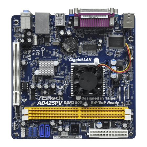
- Page 2 CPU Fan Connector (CPU_FAN1) USB 2.0 Header (USB4_5, Blue) CPU Fan System Panel Header (PANEL1, White) CPU Heatsink Chassis Speaker Header (SPEAKER 1, White) 2 x 240-pin DDR2 DIMM Slots BIOS SPI Chip (Dual Channel: DDRII_1, DDRII_2; Yellow) PCI Slot (PCI1)
- Page 3 Line In (Light Blue) COM Port Line Out (Lime) PS/2 Keyboard Port (Purple) Microphone (Pink) * There are two LED next to the LAN port. Please refer to the table below for the LAN port LED indications. LAN Port LED Indications ACT/LINK SPEED...
-
Page 4: Package Contents
This Quick Installation Guide contains introduction of the motherboard and step-by- step installation guide. More detailed information of the motherboard can be found in the user manual presented in the Support CD. Because the motherboard specifications and the BIOS software might be updated, the content of this manual will be subject to change without notice. -
Page 5: Specifications
- 1 x Serial Port: COM1 - 1 x VGA Port - 4 x Ready-to-Use USB 2.0 Ports - 1 x RJ-45 LAN Port with LED (ACT/LINK LED and SPEED LED) - HD Audio Jack: Line in / Front Speaker / Microphone Connector - 2 x SATAII 3.0 Gb/s connectors, support NCQ, AHCI and Hot... - Page 6 Overclocking may affect your system stability, or even cause damage to the components and devices of your system. It should be done at your own risk and expense. We are not responsible for possible damage caused by overclocking.
- Page 7 Before installing SATAII hard disk to SATAII connector, please read the “SATAII Hard Disk Setup Guide” on page 19 of “User Manual” in the support CD to adjust your SATAII hard disk drive to SATAII mode. You can also connect SATA hard disk to SATAII connector directly.
- Page 8 11. While CPU overheat is detected, the system will automatically shutdown. Before you resume the system, please check if the CPU fan on the motherboard functions properly and unplug the power cord, then plug it back again. To improve heat dissipation, remember to spray thermal grease between the CPU and the heatsink when you install the PC system.
-
Page 9: Screw Holes
2. Installation 2. Installation 2. Installation AD525PV / AD425PV is a Mini-ITX form factor (6.7" x 6.7", 17.0 x 17.0 cm) motherboard. Before you install the motherboard, study the configuration of your chassis to ensure that the motherboard fits into it. -
Page 10: Installation Of Memory Modules (Dimm)
Unlock a DIMM slot by pressing the retaining clips outward. Step 2. Align a DIMM on the slot such that the notch on the DIMM matches the break on the slot. The DIMM only fits in one correct orientation. It will cause permanent damage to the motherboard and the DIMM if you force the DIMM into the slot at incorrect orientation. -
Page 11: Expansion Slot (Pci Slot)
2.4 Expansion Slot (PCI Slot) There is 1 PCI slot on this motherboard. PCI slot: PCI slot is used to install expansion cards that have the 32-bit PCI interface. Installing an expansion card Installing an expansion card Installing an expansion card... -
Page 12: Jumpers Setup
PS2_USB_PWR1 Short pin2, pin3 to enable +5VSB (standby) for PS/2 (see p.2 No. 1) or USB wake up events. Note: To select +5VSB, it requires 2 Amp and higher standby current provided by power supply. ASRock AD525PV / AD425PV Motherboard... -
Page 13: Onboard Headers And Connectors
2.6 Onboard Headers and Connectors Onboard headers and connectors are NOT jumpers. Do NOT place jumper caps over these headers and connectors. Placing jumper caps over the headers and connectors will cause permanent damage of the motherboard! Serial ATAII Connectors... - Page 14 Though this motherboard provides 4-Pin CPU fan (Quiet Fan) support, the 3-Pin CPU fan still can work successfully even without the fan speed control function. If you plan to connect the 3-Pin CPU fan to the CPU fan connector on this motherboard, please connect it to Pin 1-3.
- Page 15 (see p.2, No. 6) Though this motherboard provides 24-pin ATX power connector, it can still work if you adopt a traditional 20-pin ATX power supply. To use the 20-pin ATX power supply, please plug your power supply along with Pin 1 and Pin 13.
- Page 16 STEP 2: Connect the SATA power cable to the SATA / SATAII hard disk. STEP 3: Connect one end of the SATA data cable to the motherboard’s SATAII connector. STEP 4: Connect the other end of the SATA data cable to the SATA / SATAII hard disk. 2.8 Hot Plug F 2.8 Hot Plug F...
-
Page 17: 64-Bit / Vista
Driver Installation Guide Driver Installation Guide To install the drivers to your system, please insert the support CD to your optical drive first. Then, the drivers compatible to your system can be auto-detected and listed on the support CD driver page. Please follow the order from up to bottom side to install those required drivers. -
Page 18: Untied Overclocking Technology
Untied Overclocking function, please enter “Overclock Mode” option of BIOS setup to set the selection from [Auto] to [CPU, PCIE, Async.]. Therefore, CPU FSB is untied during overclocking, but PCI buse is in the fixed mode so that FSB can operate under a more stable overclocking environment. -
Page 19: Bios Information
ROM drive. It will display the Main Menu automatically if “AUTORUN” is enabled in your computer. If the Main Menu does not appear automatically, locate and double- click on the file “ASSETUP.EXE” from the BIN folder in the Support CD to display the menus. - Page 20 1. Einführung 1. Einführung 1. Einführung Wir danken Ihnen für den Kauf des ASRock AD525PV / AD425PV Motherboard, ein zuverlässiges Produkt, welches unter den ständigen, strengen Qualitätskontrollen von ASRock gefertigt wurde. Es bietet Ihnen exzellente Leistung und robustes Design, gemäß der Verpflichtung von ASRock zu Qualität und Halbarkeit.
-
Page 21: Spezifikationen
- 1 x Serieller port: COM 1 - 1 x VGA Port - 4 x Ready-to-Use USB 2.0 Ports - 1 x RJ-45 LAN Port mit LED (ACT/LINK LED und SPEED LED) - Audioanschlüsse: Line In / Line Out / Mikrofon Anschlüsse - 2 x SATAII-Anschlüsse, unterstützt bis 3.0 Gb/s... - Page 22 - CPU/Gehäuse-Lüfteranschluss - 24-pin ATX-Netz-Header - Interne Audio-Anschlüsse - Anschluss für Audio auf der Gehäusevorderseite - 2 x USB 2.0 Buchse (unterstützt 4 USB 2.0 Ports) (siehe VORSICHT 6) BIOS - 4Mb AMI BIOS - AMI legal BIOS mit Unterstützung für “Plug and Play”...
- Page 23 Beachten Sie bitte, dass Overclocking, einschließlich der Einstellung im BIOS, Anwenden der Untied Overclocking-Technologie oder Verwenden von Overclocking-Werkzeugen von Dritten, mit einem gewissen Risiko behaftet ist. Overclocking kann sich nachteilig auf die Stabilität Ihres Systems auswirken oder sogar Komponenten und Geräte Ihres Systems beschädigen.
- Page 24 USB-Flash-Laufwerk oder die Festplatte das Dateisystem FAT32/16/12 benutzen muss. Allein der Name – OC DNA* – beschreibt es wörtlich, was die Software zu leisten vermag. OC DNA ist ein von ASRock exklusiv entwickeltes Dienstprogramm, das Nutzern eine bequeme Möglichkeit bietet, Übertaktungseinstellungen aufzuzeichnen und sie Anderen mitzuteilen.
-
Page 25: Einstellung Der Jumper
Überbrücken Sie Pin2, Pin3, um +5VSB (Standby) zu setzen (siehe S.2 - No. 1) und die PS/2 oder USB- Weckfunktionen zu aktivieren. Hinweis: Um +5VSB nutzen zu können, muss das Netzteil auf dieser Leitung 2A oder mehr leisten können. ASRock AD525PV / AD425PV Motherboard... - Page 26 1.4 Integrierte Header und Anschlüsse 1.4 Integrierte Header und Anschlüsse 1.4 Integrierte Header und Anschlüsse Integrierte Header und Anschlüsse sind KEINE Jumper. Setzen Sie KEINE Jumperkappen auf diese Header und Anschlüsse. Wenn Sie Jumperkappen auf Header und Anschlüsse setzen, wird das Motherboard unreparierbar beschädigt!
- Page 27 Geräte), wobei jedoch die Bildschirmverdrahtung am Gehäuse HDA unterstützen muss, um richtig zu funktionieren. Beachten Sie bei der Installation im System die Anweisungen in unserem Handbuch und im Gehäusehandbuch. 2. Wenn Sie die AC’97-Audioleiste verwenden, installieren Sie diese wie nachstehend beschrieben an der Front-Audioanschlussleiste: A.
- Page 28 Obwohl dieses Motherboard einen 24-pol. ATX-Stromanschluss bietet, kann es auch mit einem modifizierten traditionellen 20-pol. ATX-Netzteil verwendet werden. Um ein 20-pol. ATX-Netzteil zu verwenden, stecken Sie den Stecker mit Pin 1 und Pin 13 ein. Installation eines 20-pol. ATX-Netzteils ASRock AD525PV / AD425PV Motherboard...
- Page 29 Erscheint der Wilkommensbildschirm nicht, so “doppelklicken” Sie bitte auf das File ASSETUP.EXE im BIN-Verzeichnis der Support-CD, um die Menüs aufzurufen. Das Setup-Programm soll es Ihnen so leicht wie möglich machen. Es ist menügesteuert, d.h. Sie können in den verschiedenen Untermenüs Ihre Auswahl treffen und die Programme werden dann automatisch installiert.
-
Page 30: Contenu Du Paquet
1.1 Contenu du paquet 1.1 Contenu du paquet 1.1 Contenu du paquet Carte mère ASRock AD525PV / AD425PV (Facteur de forme Mini-ITX : 6.7 pouces x 6.7 pouces, 17.0 cm x 17.0 cm) ® Un processeur Intel Atom double-cœur D525 (AD525PV) ®... - Page 31 - Prise en charge de la technologie Hyper-Threading (voir ATTENTION 1) - Prend en charge la technologie Untied Overclocking (voir ATTENTION 2) - Prise en charge de la technologie EM64T par le CPU Chipsets - Southbridge: Intel ® NM10 Express Mémoire...
- Page 32 Connecteurs - 2 x connecteurs SATAII, prennent en charge un taux de transfert de données pouvant aller jusqu’à 3.0Go/s, supporte NCQ, AHCI et “Hot-Plug” (Connexion à chaud) (voir ATTENTION 5) - Connecteur pour ventilateur de CPU/Châssis - br. 24 connecteur d’alimentation ATX...
- Page 33 * Pour de plus amples informations sur les produits, s’il vous plaît visitez notre site web: http://www.asrock.com ATTENTION Il est important que vous réalisiez qu’il y a un certain risque à effectuer l’overclocking, y compris ajuster les réglages du BIOS, appliquer la technologie Untied Overclocking, ou utiliser des outils de tiers pour l’overclocking.
- Page 34 Pour améliorer la dissipation de la chaleur, n’oubliez pas de mettre de la pâte thermique entre le CPU le dissipateur lors de l’installation du PC.
- Page 35 3 pour choisir +5VSB (voir p.2 No. 1) (standby) et permettre aux périphériques PS/2 ou USB de réveiller le système. Note: Pour sélectionner +5VSB, il faut obligatoirement 2 Amp et un courant standby supérieur fourni par l’alimentation. ASRock AD525PV / AD425PV Motherboard...
- Page 36 Les en-têtes et connecteurs sur carte NE SONT PAS des cavaliers. NE PAS placer les capuchons de cavalier sur ces en-têtes et connecteurs. Le fait de placer les capuchons de cavalier sur les en- têtes et connecteurs causera à la carte mère des dommages irréversibles!
- Page 37 1. L’audio à haute définition (HDA) prend en charge la détection de fiche, mais le fil de panneau sur le châssis doit prendre en charge le HDA pour fonctionner correctement. Veuillez suivre les instructions dans notre manuel et le manuel de châssis afin installer votre système.
- Page 38 (voir p.2 No. 2) ien que cette carte mère offre un support de (Ventilateur silencieux) ventilateur de CPU à 4 broches , le ventilateur de CPU à 3 broches peut bien fonctionner même sans la fonction de commande de vitesse du ventilateur.
- Page 39 (ATXPWR1 br. 24) tête. (voir p.2 No. 6) Bien que cette carte mère fournisse un connecteur de courant ATX 24 broches, elle peut encore fonctionner si vous adopter une alimentation traditionnelle ATX 20 broches. Pour utiliser une alimentation ATX 20 broches, branchez à l’alimentation électrique ainsi qu’aux broches 1 et 13.
-
Page 40: Informations Sur Le Cd De Support
BIOS après le POST, veuillez redémarrer le système en pressant <Ctl> + <Alt> + <Suppr>, ou en pressant le bouton de reset sur le boîtier du système. Vous pouvez également redémarrer en éteignant le système et en le rallumant. -
Page 41: Contenuto Della Confezione
1. Introduzione Grazie per aver scelto una scheda madre ASRock AD525PV / AD425PV, una scheda madre affidabile prodotta secondo i severi criteri di qualità ASRock. Le prestazioni eccellenti e il design robusto si conformano all’impegno di ASRock nella ricerca della qualità e della resistenza. - Page 42 1.2 Specifiche Specifiche Specifiche Specifiche Specifiche Piattaforma - Mini-ITX Form Factor: 6.7-in x 6.7-in, 17.0 cm x 17.0 cm - Condensatore solido per alimentazione CPU ® Processore - processore Intel Dual-Core Atom D525 (AD525PV) ® - processore Intel Atom D425 (AD425PV) - Supporto tecnologia Hyper Threading (vedi ATTENZIONE 1) - Supporta la tecnologia overclocking “slegata”...
- Page 43 - Connettore ventolina CPU/telaio - 24-pin collettore alimentazione ATX - Connettori audio interni - Connettore audio sul pannello frontale - 2 x header USB 2.0 (supporta 4 porte USB 2.0) (vedi ATTENZIONE 6) BIOS - 4Mb AMI BIOS - Suppor AMI legal BIOS - Supporta “Plug and Play”...
- Page 44 AVVISO Si prega di prendere atto che la procedura di overclocking implica dei rischi, come anche la regolazione delle impostazioni del BIOS, l’applicazione della tecnologia Untied Overclocking Technology, oppure l’uso di strumenti di overclocking forniti da terzi. L’overclocking può influenzare la stabilità del sistema, ed anche provocare danni ai componenti ed alle periferiche del sistema.
- Page 45 Il nome stesso del software – OC DNA – dice di cosa è capace. OC DNA, una utilità esclusiva sviluppata da ASRock, fornisce un modo comodo per registrare le impostazioni OC e condividerle con gli altri. Aiuta a salvare le registrazioni di overclocking nel sistema operativo e semplifica la complicata procedura di registrazione delle impostazioni di overclocking.
- Page 46 Cortocircuitare pin2, pin3 per settare a +5VSB (standby) e (vedi p.2 Nr. 19) abilitare PS/2 o USB wake up events. Nota: Per selezionare +5VSB, si richiedono almeno 2 Ampere e il consumo di corrente in standby sarà maggiore. ASRock AD525PV / AD425PV Motherboard...
- Page 47 1.4 Collettori e Connettori su Scheda 1.4 Collettori e Connettori su Scheda I collettori ed i connettori su scheda NON sono dei jumper. NON installare cappucci per jumper su questi collettori e connettori. L’installazione di cappucci per jumper su questi collettori e connettori provocherà...
- Page 48 1. La caratteristica HDA (High Definition Audio) supporta il rilevamento dei connettori, però il pannello dei cavi sul telaio deve supportare la funzione HDA (High Definition Audio) per far sì che questa operi in modo corretto. Attenersi alle istruzioni del nostro manuale e del manuale del telaio per installare il sistema.
- Page 49 Sebbene la presente scheda madre disponga di un supporto per ventola CPU a 4 piedini (ventola silenziosa), la ventola CPU a 3 piedini è in grado di funzionare anche senza la funzione di controllo della velocità della ventola. Se si intende collegare la ventola CPU a 3 piedini al connettore della ventola CPU su questa scheda madre, collegarla ai piedini 1-3.
- Page 50 BIOS; altrimenti, POST continua con i suoi test di routine. Per entrare il BIOS Setup dopo il POST, riavvia il sistema premendo <Ctl> + <Alt> + <Delete>, o premi il tasto di reset sullo chassis del sistema. Per informazioni più dettagliate circa il Setup del BIOS, fare riferimento al Manuale dell’Utente (PDF file) contenuto nel cd di...
-
Page 51: Contenido De La Caja
ASRock. Esta Guía rápida de instalación contiene una introducción a la placa base y una guía de instalación paso a paso. Puede encontrar una información más detallada sobre la placa base en el manual de usuario incluido en el CD de soporte. - Page 52 1.2 Especificación Especificación Especificación Especificación Especificación Plataforma - Factor forma Mini-ITX: 17,0 cm x 17,0 cm, 6,7” x 6,7” - Condensador sólido para alimentación de CPU ® Procesador - Procesador Intel Atom D525 de Doble Núcleo (AD525PV) - Procesador Intel ®...
- Page 53 - Cumple con la directiva ErP/EuP (se requiere una fuente de alimentación que cumpla con la directiva ErP/EuP) (vea ATENCIÓN 12) * Para más información sobre los productos, por favor visite nuestro sitio web: http://www.asrock.com ASRock AD525PV / AD425PV Motherboard...
- Page 54 ADVERTENCIA Tenga en cuenta que hay un cierto riesgo implícito en las operaciones de aumento de la velocidad del reloj, incluido el ajuste del BIOS, aplicando la tecnología de aumento de velocidad liberada o utilizando las herramientas de aumento de velocidad de otros fabricantes.
- Page 55 ¡Gracias a OC DNA podrá guardar su configuración de OC como perfil y compartirlo con sus amigos! ¡Sus amigos podrán cargar entonces el perfil de OC en su propio sistema y disfrutar de la configuración de OC creada por usted! Recuerde que el perfil de OC creado sólo funcionará en placas base similares, por lo que sólo podrá...
- Page 56 Ponga en cortocircuito pin 2, pin 3 para habilitar +5VSB (vea p.2, N. 1) (standby) para PS/2 o USB wake up events. Atención: Para elegir +5VSB, se necesita corriente mas que 2 Amp proveida por la fuente de electricidad. ASRock AD525PV / AD425PV Motherboard...
- Page 57 1.4 Cabezales y Conectores en Placas 1.4 Cabezales y Conectores en Placas Los conectores y cabezales en placa NO son puentes. NO coloque las cubiertas de los puentes sobre estos cabezales y conectores. El colocar cubiertas de puentes sobre los conectores y cabezales provocará...
- Page 58 2. Si utiliza el panel de sonido AC’97, instálelo en la cabecera de sonido del panel frontal de la siguiente manera: A. Conecte Mic_IN (MIC) a MIC2_L.
- Page 59 Si pretende enchufar el ventilador de procesador de 3 contactos en el conector del ventilador de procesador de esta placa base, conéctelo al contacto 1-3. Contacto 1-3 conectado Instalación del ventilador de 3 contactos...
- Page 60 Para iniciar la instalación, ponga el CD en el lector de CD y se desplegará el Menú Principal automáticamente si «AUTORUN» está habilitado en su computadora. Si el Menú...
- Page 61 ASRock. ASRock Mini-ITX: 6,7 x 6,7 / 17,0 x 17,0 ASRock ASRock Serial ATA (SATA) ( ASRock AD525PV / AD425PV Motherboard...
- Page 62 Mini-ITX: 6,7 x 6,7 / 17,0 x 17,0 ASRock AD525PV / AD425PV Motherboard...
- Page 63 Hot-Plug ASRock AD525PV / AD425PV Motherboard...
- Page 64 ASRock AD525PV / AD425PV Motherboard...
- Page 65 ASRock AD525PV / AD425PV Motherboard...
- Page 66 Short Open ASRock AD525PV / AD425PV Motherboard...
- Page 67 SATAII_2 SATAII_1 ASRock AD525PV / AD425PV Motherboard...
- Page 68 PANEL1) 4 3 2 1 ASRock AD525PV / AD425PV Motherboard...
- Page 69 ATX. ASRock AD525PV / AD425PV Motherboard...
- Page 70 BIOS Setup Power-On-Self-Test – POST POST BIOS Setup POST Ctrl> + <Alt> + <Delete BIOS Setup ASRock AD525PV / AD425PV Motherboard...
- Page 71 Gratos por comprar nossa placa–mãe AD525PV / AD425PV um produto confiável feito com ASRock um estrito controle de qualidade consistente. Com um excelente desempenho, essa placa é dotada de um projeto robusto que atende a ASRock de compromisso com a qualidade e durabilidade.
- Page 72 1.2 Especificações 1.2 Especificações 1.2 Especificações 1.2 Especificações 1.2 Especificações Plataforma - Formato Mini-ITX: 6,7 pol. x 6,7 pol., 17,0 cm x 17,0 cm - Condensador Solid para alimentação da CPU ® - Processador Intel Dual-Core Atom D525 (AD525PV) - Processador Intel ®...
- Page 73 - Medição de temperatura da placa-mãe - Tacômetros de ventilador do Processador - Tacômetros de ventilador do chassis - Ventoinha silenciosa para a CPU - Monitoramento de voltagem : +12 V, +5 V, +3.3 V, Vcore Sistema - Microsoft ®...
- Page 74 AVISO Tenha em atenção que a operação de overclocking envolve alguns riscos, nomeadamente no que diz respeito ao ajuste das definições do BIOS, à aplicação da tecnologia Untied Overclocking ou à utilização de ferramentas de overclocking de terceiros. O overclocking pode afectar a estabilidade do seu sistema ou até...
- Page 75 O próprio nome do software – OC DNA diz-lhe literalmente aquilo de que é capaz. OC DNA, um utilitário exclusivo desenvolvido pela ASRock, proporciona uma forma conveniente para o utilizador gravar as definições OC e partilhar com outros. Ajuda-o a guardar o seu registo de “overclocking”...
- Page 76 +5VSB (stand by) (veja a folha 2, No. 1) para PS/2 ou eventos de wake up na USB. Nota: Para escolher +5VSB, é preciso uma corrente de stand by de 2 A ou mais. ASRock AD525PV / AD425PV Motherboard...
- Page 77 1.4 Conectores 1.4 Conectores 1.4 Conectores 1.4 Conectores 1.4 Conectores Os conectores NÃO SÃO jumpers. NÃO coloque capas de jumper sobre estes conectores. A colocação de pontos de jumper sobre os conectores causará danos irreversíveis à placa-mãe. Conector Figura Descrição...
- Page 78 Siga s instruções que aparecem no manual e no manual do chassis para instalar o sistema. 2. Se utilizar o painel de áudio AC’97, instale-o no cabeçalho de áudio do painel frontal, como a figura abaixo mostra: A. Ligue o Mic_IN (MIC) ao MIC2_L.
- Page 79 (Ventoinha silenciosa), uma ventoinha de 3 pinos para CPU poderá funcionar mesmo sem a função de controlo de velocidade da ventoinha. Se pretender ligar uma ventoinha de 3 pinos para CPU ao conector de ventoinha do CPU nesta placa-mãe, por favor, ligue-a aos pinos 1-3.
- Page 80 Se desejar acessar o Utilitário de Configuração do BIOS depois do POST, reinicie o sistema pressionando <Ctl> + <Alt> + <Del>, ou pressionando o botão de reinício no chassi do sistema. Para as informações detalhadas sobre o Utilitário de Configuração do BIOS, consulte o Manual do Usuário (arquivo PDF) no CD de suporte.
- Page 81 ASRock AD525PV / AD425PV Motherboard...
- Page 82 ASRock AD525PV / AD425PV Motherboard...
- Page 83 ASRock AD525PV / AD425PV Motherboard...
- Page 84 ASRock AD525PV / AD425PV Motherboard...
- Page 85 ASRock AD525PV / AD425PV Motherboard...
- Page 86 Short Open ASRock AD525PV / AD425PV Motherboard...
- Page 87 SATAII_2 SATAII_1 ASRock AD525PV / AD425PV Motherboard...
- Page 88 4 3 2 1 ASRock AD525PV / AD425PV Motherboard...
- Page 89 ASRock AD525PV / AD425PV Motherboard...
- Page 90 ASRock AD525PV / AD425PV Motherboard...
- Page 91 ® ® ASRock AD525PV / AD425PV Motherboard...
- Page 92 ® ® ® ® ® ASRock AD525PV / AD425PV Motherboard...
- Page 93 ® ASRock AD525PV / AD425PV Motherboard...
- Page 94 “ ” ® ® “ ” “ ” ® ® ASRock AD525PV / AD425PV Motherboard...
- Page 95 ASRock AD525PV / AD425PV Motherboard...
- Page 96 “ ” “ ” “ ” “ ” ASRock AD525PV / AD425PV Motherboard...
- Page 97 SATAII_2 SATAII_1 ASRock AD525PV / AD425PV Motherboard...
- Page 98 4 3 2 1 ASRock AD525PV / AD425PV Motherboard...
- Page 99 ASRock AD525PV / AD425PV Motherboard...
- Page 100 “ ” “ ” 1 0 0 1 0 0 1 0 0 1 0 0 1 0 0 ASRock AD525PV / AD425PV Motherboard...
- Page 101 ® ® 1 0 1 1 0 1 1 0 1 1 0 1 1 0 1 ASRock AD525PV / AD425PV Motherboard...
- Page 102 ® ® ® ® ® 1 0 2 1 0 2 1 0 2 1 0 2 1 0 2 ASRock AD525PV / AD425PV Motherboard...
- Page 103 ® ® 1 0 3 1 0 3 1 0 3 1 0 3 1 0 3 ASRock AD525PV / AD425PV Motherboard...
- Page 104 “ ” ® ® ® ® ® ® – 1 0 4 1 0 4 1 0 4 1 0 4 1 0 4 ASRock AD525PV / AD425PV Motherboard...
- Page 105 1 0 5 1 0 5 1 0 5 1 0 5 1 0 5 ASRock AD525PV / AD425PV Motherboard...
- Page 106 1 0 6 1 0 6 1 0 6 1 0 6 1 0 6 ASRock AD525PV / AD425PV Motherboard...
- Page 107 SATAII_2 SATAII_1 1 0 7 1 0 7 1 0 7 1 0 7 1 0 7 ASRock AD525PV / AD425PV Motherboard...
- Page 108 4 3 2 1 1 0 8 1 0 8 1 0 8 1 0 8 1 0 8 ASRock AD525PV / AD425PV Motherboard...
- Page 109 1 0 9 1 0 9 1 0 9 1 0 9 1 0 9 ASRock AD525PV / AD425PV Motherboard...
- Page 110 ® ® 1 1 0 1 1 0 1 1 0 1 1 0 1 1 0 ASRock AD525PV / AD425PV Motherboard...
- Page 111 ® ® 1 1 1 1 1 1 1 1 1 1 1 1 1 1 1 ASRock AD525PV / AD425PV Motherboard...
- Page 112 ® ® ® ® ® 1 1 2 1 1 2 1 1 2 1 1 2 1 1 2 ASRock AD525PV / AD425PV Motherboard...
- Page 113 ® ® 1 1 3 1 1 3 1 1 3 1 1 3 1 1 3 ASRock AD525PV / AD425PV Motherboard...
- Page 114 ® ® ® ® ® 1 1 4 1 1 4 1 1 4 1 1 4 1 1 4 ASRock AD525PV / AD425PV Motherboard...
- Page 115 ® 1 1 5 1 1 5 1 1 5 1 1 5 1 1 5 ASRock AD525PV / AD425PV Motherboard...
- Page 116 1 1 6 1 1 6 1 1 6 1 1 6 1 1 6 ASRock AD525PV / AD425PV Motherboard...
- Page 117 SATAII_2 SATAII_1 1 1 7 1 1 7 1 1 7 1 1 7 1 1 7 ASRock AD525PV / AD425PV Motherboard...
- Page 118 4 3 2 1 1 1 8 1 1 8 1 1 8 1 1 8 1 1 8 ASRock AD525PV / AD425PV Motherboard...
- Page 119 1 1 9 1 1 9 1 1 9 1 1 9 1 1 9 ASRock AD525PV / AD425PV Motherboard...
- Page 120 ® ® 1 2 0 1 2 0 1 2 0 1 2 0 1 2 0 ASRock AD525PV / AD425PV Motherboard...
- Page 121 1 2 1 1 2 1 1 2 1 1 2 1 1 2 1 ASRock AD525PV / AD425PV Motherboard...
- Page 122 ® ® 1 2 2 1 2 2 1 2 2 1 2 2 1 2 2 ASRock AD525PV / AD425PV Motherboard...
- Page 123 ® ® ® ® ® 1 2 3 1 2 3 1 2 3 1 2 3 1 2 3 ASRock AD525PV / AD425PV Motherboard...
- Page 124 ® ® 1 2 4 1 2 4 1 2 4 1 2 4 1 2 4 ASRock AD525PV / AD425PV Motherboard...
- Page 125 ® ® ® ® ® 1 2 5 1 2 5 1 2 5 1 2 5 1 2 5 ASRock AD525PV / AD425PV Motherboard...
- Page 126 ® 1 2 6 1 2 6 1 2 6 1 2 6 1 2 6 ASRock AD525PV / AD425PV Motherboard...
- Page 127 1 2 7 1 2 7 1 2 7 1 2 7 1 2 7 ASRock AD525PV / AD425PV Motherboard...
- Page 128 SATAII_2 SATAII_1 1 2 8 1 2 8 1 2 8 1 2 8 1 2 8 ASRock AD525PV / AD425PV Motherboard...
- Page 129 4 3 2 1 1 2 9 1 2 9 1 2 9 1 2 9 1 2 9 ASRock AD525PV / AD425PV Motherboard...
- Page 130 1 3 0 1 3 0 1 3 0 1 3 0 1 3 0 ASRock AD525PV / AD425PV Motherboard...
- Page 131 ® ® ® 1 3 1 1 3 1 1 3 1 1 3 1 1 3 1 ASRock AD525PV / AD425PV Motherboard...
Need help?
Do you have a question about the AD425PV and is the answer not in the manual?
Questions and answers