Advertisement
Advertisement
Table of Contents

Related Manuals for Electrolux ERF501 Series


Summary of Contents for Electrolux ERF501 Series
- Page 1 COLD APPLIANCES WITH ELECTRONIC CONTROL SYSTEM ERF501x SERVICE MANUAL Food preservation Publication number 599 83 61-99 Edition: 06/2020 - Rev. 00 FOR INTERNAL AND PARTNERS USE ONLY © ELECTROLUX HOME PRODUCTS Consumer Service - EMEA Quality & Continuous Improvement - Technical Support...
-
Page 2: Purpose Of This Manual
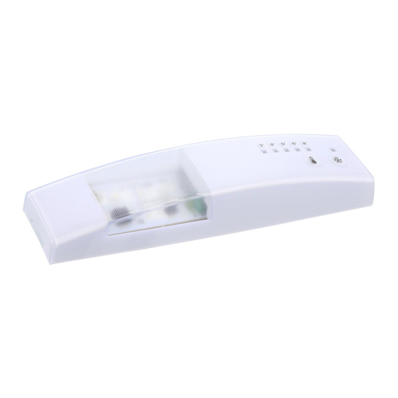
PURPOSE OF THIS MANUAL The purpose of this Service Manual is to provide Service Engineers who are already familiar with repair procedures with information regarding the PCB. The manual deals with the following topics: o PCB general characteristics o Disassembly Document Revisions Rev. - Page 3 ERF501X GENERAL CHARACTERISTICS ERF501X has two ACS power boards with an integrated UI. Technical specification Operating voltage input: 230 Vac Frequency range: 1: Temperature LED 2: Frostmatic (Superfrost) LED 3: Frostmatic (Superfrost) button 4. Temperature regulator and On/Off Reset temperature alarm by pressing any button Combi appliances This version can set both the fridge and the freezer.
- Page 4 ERF501X CONNECTORS Sidekick 4-pol. ASY_OUT JDAAS(1) ASY_IN JDAAS(2) JDAAS(3) JDAAS(4) User interface JFLASH(1) SWDDIO JFLASH(2) RESET JFLASH(3) SWD_CLK JFLASH(4) JFLASH(5) JFLASH(6) J6(2) Door switch - DOOR_SNS – 5V DC Fan - DC_PWM_LOAD_1 - 12V DC J6(4) Variable speed compressor – VSC - 12V DC J6(6) Fridge - NTC_1 J4(1-2)
- Page 5 Illumination and loads Illumination 3 LEDs Compressor Ventilator ERF501L MONTAGE A: Additional Fixation B: Fixation in compartment Q&CI - Technical Support 599 83 61-99...
- Page 6 REPLACE THE CONTROL BOX Remove the cover of the control Remove the screw and take out the control unit Unplug the connecting wire and replace the control box Q&CI - Technical Support 599 83 61-99...
- Page 7 SERVICE MODE ERF501X Activation of service mode depends on type of appliance and the UI. Service mode can be started with a cold or warm appliance. The only exception is when testing the digital input heater switch that requires a cold appliance. There are two ways of activating service mode depending on if the appliance is built-in or freestanding: Activate service mode on built-in appliances Command...
- Page 8 SERVICE MODE LED COMBINATIONS Each step of service mode is identified by a unique index coded by LEDs. Each LED can assume three states, on, off or blinking. It is not possible to move service mode backwards, complete the sequence to go back to a required phase/component.
-
Page 9: Digital Output Test
Digital output test Note that every Digital output test is coded with the first left LED switched off and the second left LED switched on. Digital output Fridge light blinking Zero-degree light blinking blinking Fridge Evaporator fan blinking Fridge fan blinking Zero-degree fan blinking... -
Page 10: Digital Input Test
Digital input test Note that every Digital input test is coded with the first two left LED switched on. Digital input Fridge door Freezer door Zero-degree door blinking Heater switch blinking Ice maker blinking Paddle switch blinking blinking Rapid drink cooler Ice bin switch Bail arm Digital input... -
Page 11: Temperature Alarm
ALARMS 501X Temperature alarm The LED blinks and an alarm sounds if the temperature moves outside a set threshold. • The LED continues to blink until the alarm is reset by pushing the Reset button for 3 seconds. • The LED turns off automatically when the temperature returns to within the temperature threshold. No other buttons work on the UI until the alarm is reset.
Need help?
Do you have a question about the ERF501 Series and is the answer not in the manual?
Questions and answers