Table of Contents
Advertisement
Quick Links
Advertisement
Table of Contents

Related Manuals for lb PA Series

Summary of Contents for lb PA Series
- Page 1 Operation Manual Compact Amplifiers with/without DSP...
- Page 2 4 x 2 DSP matrix to get managed. The analog models can be remotely controlled via VCAs and remote ON/OFF contacts, the DSP versi- ons are configured with our browser-based LB AUDIO CONTROL App and controlled with network commands, e.g. via media controls.
-
Page 3: Table Of Contents
Block Diagram .............................. 20 Technical Data ............................... 21 Dimensions (all Models) ..........................22 Accessories ..............................23 LB AUDIO CONTROL App ........................24 - 27 Detailed technical information can be found in the product-specific data sheets and on our website: https://www.lb-lautsprecher.de/en/Amplifiers... -
Page 4: Important Savety Information
Improper use will invalidate the warranty! Disclaimer LB is not liable for damage to speakers or other equipment caused by negligence or in cases where the product has been used for something other than its intended purpose. In particular, lb is not liable for lost earnings or other financial losses incurred by the purchaser. -
Page 5: Performance Features
Performance Features Cinch Sym. SPDIF DANTE DSP Control Ext. Output Power Models Input Input Input Input Inputs Network- 2 Ohms 4 Ohms 8 Ohms com- mands PA-S 230 • • 2 x 30 W 2 x 30 W PA-S 250 •... -
Page 6: Pa-S 230
Front: Controls (Compact Amplifier without DSP) PA-S 230 Power switch The amplifier switches on with a delay of approx. 3 seconds. LED STANDBY / ON The LED lights up red in STANDBY, green when the amplifier is switched on and yellow in Sleep. - Page 7 Back: Controls (Compact Amplifier without DSP) PA-S 230 1 IEC Connector (Power cord is included) 5 AUTO ON/STEADY ON – DIP switch In the upper position the channel pair operates in AUTO-ON/ 2 Speaker outputs Fix the speaker cables to the screw-type terminals. OFF mode and switch into an idle state (SLEEP) automatically The speaker impedance should not fall below 4 ohms.
-
Page 8: Block Diagram
Block Diagram PA-S 230 Schematic PA-S 230 POWER OUT 1 30 WATTS Signal Management POWER OUT 2 30 WATTS AUTO/STEADY ON GROUND/ Channel 1+2 LIFT MAINS 90 ...250 VAC STAND BY CONTACT 50 Hz POWER ON/OFF (front) -
Page 9: Technical Data
Technical Data PA-S 230 Inputs ..............2 × Line In Cinch Nom. input level ........... 0 dBU Max. input level ............ + 20 dBU Input impedance ........... 20 kOhms Load impedance ............ ≥ 4 Ohms Outputs ..............2 × Speaker Out bis 2 × 2,5 mm², (screwtype terminals, pluggable) Output power 2 Ohms .............. -
Page 10: Pa-S 250 / Pa-S 2100 / Pa-S 2200
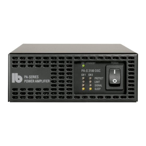
Front: Controls (Compact Amplifier without DSP) PA-S 250 / PA-S 2100 / PA-S 2200 Power switch LED displays The amplifier switches on with a delay of approx. SLEEP – the corresponding power amplifier channel 3 seconds. is in power-saving mode and is automatically reactivated when there is a signal. - Page 11 Back: Controls (Compact Amplifier without DSP) PA-S 250 / PA-S 2100 / PA-S 2200 IEC Connector (Power cord is included) GROUND LIFT-Switch In the GROUND position (down) audio ground is directly Speaker outputs Fix the speaker cables to the screw-type terminals. connected to the mains ground.
-
Page 12: Block Diagram
Block Diagram PA-S 250 / PA-S 2100 / PA-S 2200 Schematic PA-S 2200 POWER OUT 1 INPUT 1 50 / 100 / 200 WATTS sym. VCA 1 Signal Management INPUT 2 POWER OUT 2 sym. 50 / 100 / 200 WATTS VCA 2 AUTO/STEADY ON Channel 1+2... -
Page 13: Technical Data
Technical Data PA-S 250 / PA-S 2100 / PA-S 2200 Inputs ..............2 × Line In sym. + 2 × Line In Cinch Nom. input level ........... + 4/-6 dBU, switchable Max. input level ........... + 20 dBU Input impedance ............ 20 kOhms Load impedance ............ -
Page 14: Pa-S 250 Dsc / Pa-S 2100 Dsc / Pa-S 2200 Dsc
Front: Controls (Compact Amplifier with DSP) PA-S 250 DSC / PA-S 2100 DSC / PA-S 2200 DSC Power switch LED displays The amplifier switches on with a delay of approx. SLEEP – the corresponding power amplifier channel is in 3 seconds. power-saving mode and is automatically reactivated when there is a signal. - Page 15 Back: Controls (Compact Amplifier with DSP) PA-S 250 DSC / PA-S 2100 DSC / PA-S 2200 DSC IEC Connector (Power cord is included) This reduces power consumption significantly. In the lower position the channel pair is active permanently Speaker outputs Fix the speaker cables to the screw-type terminals.
-
Page 16: Block Diagram
Block Diagram PA-S 250 DSC / PA-S 2100 DSC / PA-S 2200 DSC Schematic PA-S 250 / 2100 / 2200 DSC DSP (Signal Processing) Gain, Filters, Gain, Filters, POWER OUT 1 INPUT 1 Delay, Limiter, Delay, Limiter, 50 / 100 / 200 WATTS sym. -
Page 17: Technical Data
Functions .............. 4 × 2 mixer matrix, Lowpass, Highpass and 10 fully parametric filters per input/output: bell, high shelf, low shelf, high-pass, low-pass. Delay up to 400 ms, limiter and compressor per input/output, 40 presets App ............... LB AUDIO CONTROL Download Website: www.lb-lautsprecher.de/Download-Software Remote control ............. Via network commands Interface ............... -
Page 18: Front/Back
Front: Controls (Compact Amplifier with DSP and DANTE interface) PA-S 250 DSC DANTE / PA-S 2100 DSC DANTE / PA-S 2200 DSC DANTE Power switch LED displays The amplifier switches on with a delay of approx. SLEEP – the corresponding power amplifier channel is in 3 seconds. - Page 19 Back: Controls (Compact Amplifier with DSP and DANTE interface) PA-S 250 DSC DANTE / PA-S 2100 DSC DANTE / PA-S 2200 DSC DANTE 1 IEC Connector (Power cord is included) 9 GROUND LIFT-Switch In the GROUND position (down) audio ground is directly 2 Speaker outputs Fix the speaker cables to the screw-type terminals.
-
Page 20: Block Diagram
Block Diagram PA-S 250 DSC DANTE / PA-S 2100 DSC DANTE / PA-S 2200 DSC DANTE Schematic PA-S 2200 DSC DANTE DSP (Signal Processing) Gain, Filters, Gain, Filters, POWER OUT 1 INPUT 1 Delay, Limiter, Delay, Limiter, 50 / 100 / 200 WATTS sym. -
Page 21: Technical Data
Functions .............. 4 × 2 mixer matrix, Lowpass, Highpass and 10 fully parametric filters per input/output: bell, high shelf, low shelf, high-pass, low-pass. Delay up to 400 ms, limiter and compressor per input/output, 40 presets App ............... LB AUDIO CONTROL Download Website: www.lb-lautsprecher.de/Download-Software Remote control ............. Via network commands Interface ............... -
Page 22: Dimensions All Models
Dimensions all Models Dimensions PA-S 250 DSC / PA-S 250 DSC DANTE Front Sides Dimensions PA-S 250 DSC / PA-S 250 DSC DANTE Front Sides Backside With DANTE Backside With DANTE Mounting plate (optional) Bottom Mounting plate (optional) Bottom Screws M4 Screws M4 Dimensions PA-S 230 Dimensions PA-S 250... -
Page 23: Accessories
Accessories Mounting plate for PA-S Series MP-PA-S 100 V transformer module, 2 x 50 Watts, toroidal core PA-T 2050 100 V transformer module, 100 Watts, toroidal core PA-T 100 100 V transformer module, 200 Watts, toroidal core PA-T 200 Rack cradle 19“, 1 U for 4 x PA-S 230 - 2200, PA-T 1U 4 ×... -
Page 24: Lb Audio Control App
When opening the LB AUDIO CONTROL app, the OVERVIEW window opens first. All LB devices present in the network are displayed here. In addition, virtual demo devices can also be inserted via the menu. Changes to the device name or the IP configuration must be confirmed using the save button. - Page 25 DEVICE Window The open device with all inputs and outputs is displayed in the DEVICE window. The input and output settings can be made here. Zoom +/- Menu Fields for labeling of the channels Input-/Output- Level-Meter +Limit (yellow) +Clip (red) Display and numerical entering of the...
- Page 26 CHANNEL Windows The settings of the Input Window individual channels can be made in the CHANNEL windows. Delay up to 400 ms Limiter Compressor per channel per channel per channel Input Gain + Level Meter Output Window Output Gain + Level Meter Invert: rotates the phase of the...
- Page 27 LB AUDIO CONTROL Network commands SETTINGS FUNCTION EXAMPLE URLS MUTE <DSC IP>/cmds/mute/<CH>/<i/o> Mute output 2: http://192.168.0.100/cmds/mute/2/o UNMUTE <DSC IP>/cmds/unmute/<CH>/<i/o> Unmute input 3: http://192.168.0.100/cmds/unmute/3/i GAIN <DSC IP>/cmds/gain/<CH>/<i/o>/<value> Gain input 1 auf -4,8 dB: http://192.168.0.100/cmds/gain/1/i/-4.8 MIXER <DSC IP>/cmds/mixer/<CH OUT>/o/<CH IN>/<value> Input mixer output 1, input 3 + 4 to -30 dB: http://192.168.0.100/cmds/mixer/1/o/3/-30...
- Page 28 Beschallungstechnik GmbH info@lb-lautsprecher.de www.lb-lautsprecher.de www.feiner-hoeren.de Photo: Nationalmuseum Munich / Multi-zone sound @LB_Audio_Components system for gastronomy and events Tel +49 89 1893109-0 · Fax -29 Kapellenstr. 10 2/2024. Changes and errors excepted. 85622 Feldkirchen / Munich © LB Lautsprecher und Beschallungstechnik GmbH...
Need help?
Do you have a question about the PA Series and is the answer not in the manual?
Questions and answers