Advertisement
User Manual
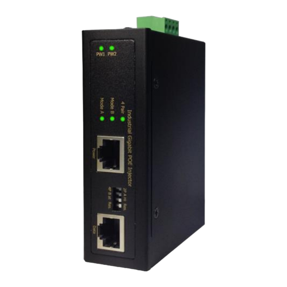
MS657032X-24
Industrial GBE High Power PoE Injector up to 60W,
IEEE802.3af/at, 2x RJ-45 Data In/ PoE Out, internal step-up
DC converter 24...56VDC power input, -40...+75°C
CE MARKING
This equipment complies with the requirements relating to electromagnetic
compatibility, EN 55022 class A for ITE, the essential protection requirement of
Council Directive 2004/108/EC on the approximation of the laws of the Member
States relating to electromagnetic compatibility.
Company has an on-going policy of upgrading its products and it may be possible
that information in this document is not up-to-date. Please check with your local
distributors for the latest information. No part of this document can be copied or
reproduced in any form without written consent from the company.
Trademarks:
All trade names and trademarks are the properties of their respective companies.
Advertisement
Table of Contents

Related Manuals for Microsens MS657032X-24

Summary of Contents for Microsens MS657032X-24
- Page 1 User Manual MS657032X-24 Industrial GBE High Power PoE Injector up to 60W, IEEE802.3af/at, 2x RJ-45 Data In/ PoE Out, internal step-up DC converter 24…56VDC power input, -40…+75°C CE MARKING This equipment complies with the requirements relating to electromagnetic compatibility, EN 55022 class A for ITE, the essential protection requirement of Council Directive 2004/108/EC on the approximation of the laws of the Member States relating to electromagnetic compatibility.
-
Page 2: Remote Switch
NOTE: Always make sure the total length of the TX cable DOES NOT exceed 100 meter. Total length is defined as length A + length B. Copyright © 2015, All Rights Reserved. Length A + Length B < 100 meter Remote Switch Maximum total cable length is 100 meter. -
Page 3: Installation Package
Installation package This unit can be installed by Din-rail mounted or wall-mounted. Din-rail brackets and wall- mounted bracket are included at delivery. Din-rail bracket Two wall mount brackets 4-pin terminal block Power connection This unit is equipped with POE capability to deliver 30 W and 60 W POE power. The provided 4 pin terminal block can be connected with 48 VDC to 56 VDC power source. -
Page 4: Led Indicator
LED indicator PW—Power 1, Power 2 Mode A Green LED ON -- For End-Span POE power 1,2,3,6 Mode B Green LED ON -- For Mid-Span POE power 4,5,7,8 4 Pair amber LED ON – Both 4 pair are delivering POE power. -
Page 5: Dip Switch Setting
Dip Switch setting This unit is equipped with 4-pin DIP switches which allow users to set the desired POE power setting to meet your desired POE network. Refer to the setting shown below: 2 pair 30 W is selected 4 pair 60 W is selected (DEFAULT) Mode A End-Span is selected (DEFAULT) Mode B Mid-Span is selected High power 36 W is selected (DEFAULT) -
Page 6: Specifications
Specifications IEEE 802.3 10Base-T Ethernet IEEE 802.3u 100Base-TX Fast Ethernet IEEE 802.3ab 1000Base-T Gigabit Ethernet IEEE Standard IEEE802.3af for POE IEEE802.3at for POE+ 1x RJ-45 10/100/1000Base-T Data 1x RJ-45 10/100/1000Base-T PSE with POE Network Connector : Output power UTP/STP above Cat.5e Cable Network Cable EIA/TIA-568 10-ohm (100 m) Protocol... - Page 7 Provide 4-pin terminal block Wire range: 0.34mm to 2.5mm Solid wire (AWG):12-24/14-22 Removable Terminal Block Stranded wire(AWG): 12-24/14-22 Torque:5lb-In/0.5Nm/0.56Nm Wire Strip length: 7-8mm Operating Temperature -40℃...75℃ fully tested 5% to 95% (Non-condensing) Operating Humidity Storage Temperature -40℃...85℃ MTBF (mean time between 510,304 h (MIL-HDBK-217F) at 25°C failure) Housing...
-
Page 8: Housing Dimensions
Housing Dimensions...
Need help?
Do you have a question about the MS657032X-24 and is the answer not in the manual?
Questions and answers