
Related Manuals for Nidec Roboteq SBS1 Series

Summary of Contents for Nidec Roboteq SBS1 Series
- Page 1 Safety Brake Switch SBS1xxyy Product Manual V1.0, Feb 10, 2024 Disclaimer: This document is subject to change. Visit www.roboteq.com to download the latest revision of this manual. ©Copyright 2022 Roboteq, Inc...
- Page 2 SBS1xxyy UL Conditions of Acceptability (CofAs) Use - For use only in complete equipment applications where the acceptability of the combination is determined by Underwriters Laboratories Inc. 1. The device is intended to be used in a pollution degree 2 environment. 2.
- Page 3 SBS1xxyy SAFETY PRECAUTION For the safe operation of this product, it is essential to adhere to the following safety instructions. Compliance will prevent injuries to personnel and avoid damage to the equipment. Warning This symbol indicates that incorrect operations may result in personal injury. This symbol indicates that incorrect operations may cause equipment Caution damage or loss of warranty rights.
-
Page 4: Table Of Contents
SBS1xxyy Table of Contents Section 1: Overview ............................. 4 Section 2: Operating Features ........................7 2.1 Principle of Operation ........................7 2.2 Three-phase short ..........................8 2.3 Safety Engagement of the Motor Brake .................... 9 2.4 Built-in Diagnostics and SBS Status Output ..................9 2.5 Safety System Operation ......................... -
Page 5: Section 1: Overview
SBS1xxyy Overview Section 1 Roboteq’s Safety Brake Switch (SBS) family units are motor drive subsystems designed to work in conjunction with a wide variety of power sources and motor drives in order to perform rapid and safe motor braking in high-inertia applications, such Mobile Robots, where serious injury to person and/or expensive material damage can occur if the motor runs out of control. - Page 6 SBS1xxyy Key Features • Patented design and technique (patent numbers: US20230144377A1, US20230141274A1) • Functionally safe design according to ISO 13849-1, Category 3, Performance Level d • Product safety complies to UL508/CSAXXX (UL file: E536426) • Reliable motor braking control based on two safety signals from the safety master controller •...
- Page 7 SBS1xxyy Vertical Molex variant DC Volts Motor Brake Peak braking/Continuous Reference Power Connectors (Max) Supply Current Molex Mega-Fit Main battery SBSM1360VMxxyy 100A/20A Slim Vertical Molex Mega-Fit Auxiliary battery SBSM1360VAxxyy 100A/20A Slim Vertical Right-angle Molex variant DC Volts Motor Brake Peak braking/Continuous Reference Power Connectors (Max)
-
Page 8: Section 2: Operating Features
SBS1xxyy Operating Features Section 2: 2.1 Principle of Operation Unlike conventional systems, which leave the motor windings floating when the Safe Torque Off (STO) feature is activated, systems incorporating the Safety Brake Switch (SBS) adopt a different strategy. The SBS initiates motor braking shortly after the motor drive enters the STO state by executing a 3-phase short across the motor phases. -
Page 9: Three-Phase Short
SBS1xxyy Motor STO Inputs Com. Bus Brake + Safety Control Output 1 Safety Control Output 2 Brake - SBS Status Safetey Input 1 Safety Control Input 1 Safety Output 1 Safety Control Input 2 Safety Output 2 Safety Brake Control 1 Safety Output 3 Safety Brake Control 2 Safety Output 4... -
Page 10: Safety Engagement Of The Motor Brake
SBS1xxyy 2.3 Safety Engagement of the Motor Brake The Safety Brake Switch activates the motor brake at intervals defined by the specific device variant, following the activation of the STO signal. The motor brake can be controlled either exclusively through the Safety Brake Switch or in conjunction with the motor drive. -
Page 11: Safety System Operation
SBS1xxyy 2.5 Safety System Operation This section examines the states of a safety system consisting of a safety master device (such as a safety PLC, safety controller or any other type of safety device), a Roboteq drive, and a Safety Brake Switch. While the Safety Brake Switch can work with any motor drive equipped with STO, this demonstration will focus on a Roboteq drive due to the variations allowed by the standard in STO implementation across different manufacturers. - Page 12 SBS1xxyy Safety Brake Switch • Upon initiation, the Safety Brake Switch sets both Safety Control outputs to a low state, causing the drive to enter STO mode. Once both safety control inputs are high, SBS performs its diagnostic tests. If the circuits under test are functional, the Safety Brake Switch relays the safety master controller’s outputs to the motor drive.
- Page 13 SBS1xxyy S1=S2=High Start SBS self-check SBS Status: Low SBS Status: Low STO1=STO2=High MC Status: STO MC Status: STO Failure at SBS Failure STO Fault at SBS Hard fault MC self-check SBS Status: High SBS Status: Low SBS Status: High MC Status: Failure at SBS MC Status: STO MC Status: STO...
-
Page 14: Section 3: Hardware Connections
SBS1xxyy Hardware Connections Section 3: 3.1 Function Block Diagram The connection diagram in Figure 3.1-1 includes only the essential components required for the safety system operation. It does not incorporate elements that ensure the system's proper and safe functioning, such as emergency contactors and fuses. This diagram is provided solely to facilitate understanding of the module's operation. -
Page 15: Power Wiring Diagram
SBS1xxyy For dual-channel operation, the Safety control signals should be routed from the PLC to the motor drive passing through the two Safety Brake Switches connected in series. Figure 3.1-2 presents a dual-channel function block diagram with two Safety Brake Switches. DUAL CHANNEL MOTOR MOTOR... - Page 16 SBS1xxyy SW1 Main On/Off Switch 1A F2 1A PwrCtrl Ground Backup Battery Motor Motor Controller Ground VMot I/O Connector Do not Resistor Connect! 100Ohm, 5W STO Signals VMot Emergency Contactor or Cut-off Switch Safety Brake Switch Ground Brake Connector Connector Status Connector Do not...
-
Page 17: Connection Considerations
SBS1xxyy 3.2.1 Connection Considerations Note 1 (Switches): For any application where there's a risk of property damage or personal injury due to malfunctions in both the motor drive and Safety Control Switch, an external emergency contactor (SW2) is essential. The battery should be permanently connected to both the Safety Brake Switch and the motor drive. -
Page 18: Safety Considerations
SBS1xxyy 3.2.2 Safety considerations Caution Always ensure correct polarities to prevent system damage. It is imperative that the system parts are connected as shown in the wiring diagram in order to ensure safe and trouble-free operation. All connections shown are mandatory. Important Note In case of battery disconnection at the Safety Brake Switch side, the motor brake will be engaged regardless of the motor drive brake driving circuitry state. -
Page 19: Section 4: Pin Identification And Configuration
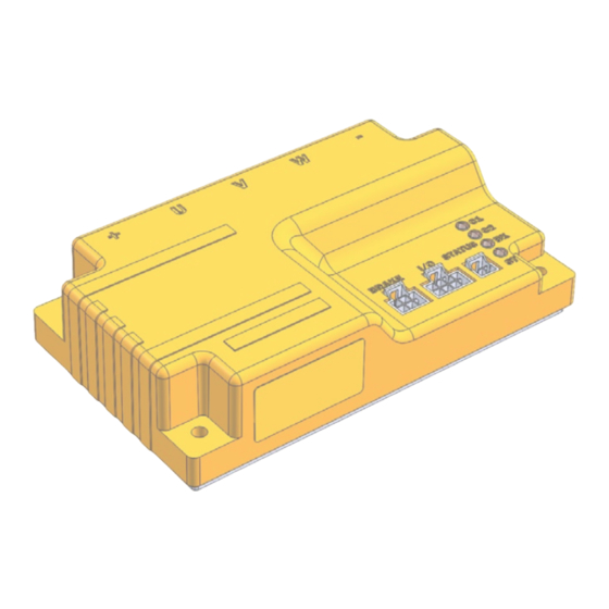
SBS1xxyy Pin Identification and Configuration Section 4: 4.1 Components and Layout The main components of the Safety Brake Switch, excluding the power connectors, are highlighted in Figure 4.1-1. Figure 4.1-1. Safety Brake Switch top view. At the bottom right corner of the board, there are connectors for the motor brake (X1), input and output control signals (X2), and status output (X3). -
Page 20: Power Terminals Identifications And Connection
SBS1xxyy 4.2 Power Terminals Identifications and Connection Power connections of the Safety Brake Switch are presented in Figure 4.2-1 for the three product variants. Each connection is double, facilitating the connectivity between the Safety Brake Switch, motor drive, motor and main battery. Figure 4.2-1. -
Page 21: Motor Brake Connection
SBS1xxyy Table 4.2.-1. PCB and mating connector models. Variant Fast-On Molex Vertical Molex PCB connector 1266 768290102 768250002 Mating connector 62998-2 1700010102 1700010102 62998-2 1700010102 Figure 4.2-2. Fast-on and Molex mating connectors Important Note Use AWG8 wire for the FASTON variant and 12 AWG wire for the MOLEX variant. For FASTON variants, ensure cables do not exert pull force on connectors;... - Page 22 SBS1xxyy Table 4.3-1. Motor brake connector. Signal Description Return ground Aux Brake- Auxiliary Motor brake coil negative connection to motor drive Brake- Motor brake coil negative connection Return ground Brake Supply Optional external 12/24V power supply for motor brake Brake+ Motor brake coil positive connection 1053101106 1053081206...
- Page 23 SBS1xxyy Figure 4.3-4 illustrates the motor brake connections when using an external battery (1), when using the Vmot voltage without PWM (2) and when the Vmot voltage is modulated by the motor drive’s open collector output (3). Figure 4.3-4. Motor brake connections. (1) External battery, (2) Vmot brake voltage and (3) Vmot brake voltage with PWM External Supply Connections: The external power supply must be connected to the dedicated pins of the X1 connector (Brake supply and GND).
-
Page 24: Safety Inputs/Outputs Connection
SBS1xxyy 4.4 Safety Inputs/Outputs Connection The safety control inputs are connected using the X2 connector which is highlighted in figure 4.4-1. The safety inputs connector is an 8-pin Molex Nano-Fit vertical header with reference number 1053101108. The corresponding mating connector model is 1053081208. Pin assignment is detailed in Table 4.4-1, and pin numbering is illustrated in Figure 15. -
Page 25: Safety Brake Switch Status
SBS1xxyy The safety brake control inputs are active-low and are used to immediately engage the motor brake, overriding any preset delays. The inputs are redundant and should be kept at the same state (high or low). Table 6 demonstrates the impact of the safety brake control inputs on the motor brake during the different states of the safety control inputs. -
Page 26: Led Indicators And Error Codes
SBS1xxyy The status connector employs a 2-pin Molex Nano-Fit vertical header, referenced as 1053091102. The suggested mating connector model is 1053071202. Pin assignment details can be found in Table 4.5-1, and pin numbering is illustrated in Figure 4.5-2. Table 4.5-1. Safety Brake Switch status connector. Connector X3 Pin Signal Description... - Page 27 SBS1xxyy Table 4.6-1 presents the actual Safety Brake Switch status for each LED state. Table 4.6-1 LED indicator states and Safety Brake Switch Status. LED Indicator LED Color LED ON LED OFF LED CH1 Blue Float power connections Three phase short LED CH2 Blue Float power connections...
- Page 28 SBS1xxyy Table 4.6-2 provides examples of blinking patterns and their corresponding codes. Table 4.6-2 LED pattern examples. Blinking Pattern Reported Code 0.5.4 1.0.6 1.2.4 0.0.1 It's important to note that while the reported codes contain multiple digits, only the first digit holds pertinent information relevant to troubleshooting and user understanding.
-
Page 29: Section 5: Electromechanical Specifications
SBS1xxyy Electromechanical Specifications Section 5 5.1 Absolute Maximum Values The values in Table 8 should never be exceeded, permanent damage to the Safety Brake Switch may result. Table 5.1-1. Safety Brake Switch absolute maximum operating values. Parameter Variant Measured Point Units Battery Leads Voltage Vmot to Ground... -
Page 30: Power Stage Electrical Specifications
SBS1xxyy 5.2 Power Stage Electrical Specifications Ambient temperature at 25 C is considered for the values presented in Table 9. Table 5.2-1. Electrical specifications of Safety Brake Switch at 25 Measured Point Model Parameter Units Input Voltage Vmot to Ground 0 (1) Volts Pre-charge time... -
Page 31: Motor Brake Electrical Specifications
SBS1xxyy 5.3 Motor Brake Electrical Specifications Table 5.3-11. Electrical specifications of motor brake control circuitry on the Safety Brake Switch. Parameter Measured Point Model Min Typ Max Units Input Voltage Vmot or Brake Supply X1 - pin 5 to Volts Ground Output Voltage X1 - pin 2, 3, and 6 to Ground... -
Page 32: Environmental Specifications
SBS1xxyy Table 5.5-1. (continued) Electrical specifications of the Safety Brake Switch inputs and outputs. Parameter Measured Point Model Units Safety Brake Control Input Ground to Input pins Volts Signal Voltage (High Level) Safety Brake Control Input Ground to Input pins Volts Signal Voltage (Low Level) SBS Status Output Signal... -
Page 33: Thermal Specifications
SBS1xxyy Table 5.7-2. Safety Brake Switch three-phase short safety specifications. Three-phase short Metric acc. To ISO 13849-1 Value 4.29E-08 1/h MTTFd >100 years Performance Level Category Table 5.7-3. Safety Brake Switch motor brake safety specifications. Motor brake control Metric acc. To ISO 13849-1 Value 4.29E-08 1/h MTTFd... -
Page 34: Mechanical Specifications
SBS1xxyy Important Note When the Safety Brake Switch is active, heat will be generated on the Safety Brake Switch components and must be evacuated. Therefore, adequate cooling is required and can be by having the bottom edges of the case making contact with a metallic surface (chassis, cabinet). - Page 35 SBS1xxyy Figure 5.8-2. SBSM13XXV main dimensions. Figure 5.8-3. SBSM13XX main dimensions. ROBOTEQ SAFETY BRAKE SWITCH V1.0 P A G E | 34...
-
Page 36: Section 6: Installation And Maintenance
SBS1xxyy Installation and Maintenance Section 6: Important Note Safety Brake Switch must be tested before first installation and at least every three months. The sequence for the quick Safety Brake Switch test is: 1. Activate safety control inputs (Safety_Control_Input_CH1 and Safety_Control_Input_CH2 at low logic level) 2. - Page 37 SBS1xxyy Important Note During the Safety Brake Switch self-check process, the output signals to the motor drive are forced at low level by the SBS internal circuit and the motor drive remains at STO state until the SBS successfully completes the self-check. In order to have maximum response at STO implementation, user/installer/integrator should use voltage source with low output capacitance.
Need help?
Do you have a question about the Roboteq SBS1 Series and is the answer not in the manual?
Questions and answers