Table of Contents
Advertisement
Quick Links
BLE 5.1, 802.15.4 Modules BM833A/AF, BM833/F/E
BluNor BM833/A are powerful, highly flexible, ultra low power Bluetooth Low Energy (BLE) modules using
Nordic nRF52 SoC. With an ARM Cortex
multi-protocol transceiver, and an integrated PCB trace antenna or an u.FL for external antenna. It allows faster
time to market with reduced development cost.
BM833A/AF are designed to minimize PCB cost and to maximize efficiency in
production line dedicated for Bluetooth modules. The cost of using BM833A
module can be lower than designing-in SoC at any quantity. At low cost,
BM833A are full feature modules. Inductors for DCDC converter are integrated.
All 32 GPIOs are accessible.
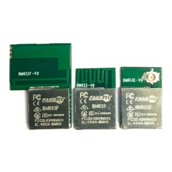
BM833/F/E, nRF52833 modules have compatible footprint for upgrading. They
offer more GPIOs, more memories, +8 dBm TX.
"Max. TX, FCC" is the maximum TX power at antenna input measured in FCC certification testings. BM833E
max. TX power is +14 dBm with FCC certified ANT060.
BM833A Specifications:
Nordic nRF52 with ARM Cortex M4 at 64 MHz.
Supported data rate:
BLE 5.1: 2Mbps, 1Mbps, 500kbps, 125kbps
IEEE 802.15.4-2006: 250 kbps
Proprietary 2.4 GHz: 2 Mbps, 1Mbps
Angle-of-Arrival (AoA) and Angle-of-Departure
(AoD) direction finding using Bluetooth.
RSSI, 1 dB resolution
Serial Wire Debug (SWD)
Nordic SoftDevice Ready
Over-the-Air (OTA) firmware update
Flash/RAM: 192KB/24KB
32 General purpose I/O pins
12 bit/200KSPS ADC, 8 configurable channels
with programmable gain.
2X SPI Master/Slave (8Mbps)
4-channel pulse width modulator (PWM)
Low power comparator
2-wire Master/Slave (I
Digital microphone interface (PDM)
UART (with CTS/RTS and DMA)
Model Summaries
module
BM833A
SoC
nRF52811 QFAA
Flash/RAM
192KB/24KB
Size
10.2x15x1.9mm
GPIO
Operating temp.
-40
o
Max. TX, FCC
+4.81 dBm
Antenna
PCB trace
Est. BLE Range
680M at 125Kbps
FCC ID
X8WBM833A
ISED
4100A-BM833A
TELEC
201-190840/00
CE, RCM
Certified
QDID
M4(F) MCU, up to 512KB flash, 128KB RAM, embedded 2.4GHz
TM
C compatible)
2
BM833AF
nRF52811 QFAA
192KB/24KB
15x20.6x1.9mm
32
C to +85
C
-40
C to +85
o
o
+4.81 dBm
High perform. PCB
1500M at 125 Kbps 1400M at 125 Kbps
X8WBM833A
4100A-BM833A
201-190840/00
Certified
138767
20 channel CPU independent Programmable
Peripheral Interconnect (PPI).
Quadrature Demodulator (QDEC)
AES HW encryption
3 x 32 bit timer with counter mode
2x realtime counter
SoC receiver Sensitivity: -97 dBm at 1Mbps;
-104 dBm at 125 kbps
SoC TX power: +/- 0 dBm; programmable 4
dBm to -20dBm in 4 dB steps.
Operation voltage: 1.7V to 3.6V
4.6 mA peak current at RX or +0dBm TX.
Integrated DC-DC converter.
Embedded inductors for DCDC converter
Major BM833 Enhancement
Cortex M4F at 64 MHz
Max SoC TX power: +8 dBm.
NFC-A tag interface for OOB pairing
Secure boot ready
1.7V to 5.5V supply voltage
USB 2.0 full speed controller (12 Mbps)
BM833
nRF52833 QIAA
512KB/128KB
10.2x15x1.9mm
32
42
C
-40
C to +105
C
o
o
o
+8.16 dBm
PCB trace
X8WBM833F
4100A-BM833F
201-19838/00
Certified
138767
138767
1
Ver 1.07 Feb. 2021
BM833F
BM833E
nRF52833 QIAA
nRF52833 QIAA
512KB/128KB
512KB/128KB
15x20.6x1.9mm
10.2x15x1.9mm
42
-40
C to +105
C
-40
C to +105
o
o
o
+8.16 dBm
+8.16 dBm
High perform. PCB
u.FL
2300M at 125Kbps
3400M at 125 Kbps
X8WBM833F
X8WBM833F
4100A-BM833F
4100A-BM833F
201-19838/00
201-19838/00
Certified
Certified
138767
42
C
o
138767
Advertisement
Table of Contents

Related Manuals for Fanstel BM833A


Summary of Contents for Fanstel BM833A
- Page 1 PCB trace antenna or an u.FL for external antenna. It allows faster time to market with reduced development cost. BM833A/AF are designed to minimize PCB cost and to maximize efficiency in production line dedicated for Bluetooth modules. The cost of using BM833A module can be lower than designing-in SoC at any quantity.
-
Page 2: Table Of Contents
Mechanical Drawings BM833AF ........................Mechanical Drawings BM833F ........................BM833A Pin Functions ............................ BM833 Pin Functions ............................Mounting BM833, BM833A on the Host PCB ....................Mounting BM833F and BM833AF on the host PCB ..................4. Evaluation Board ............................. Nordic Development Environment ........................ -
Page 3: Introduction
Connection to an external NFC (Near Field Communication) antenna is provided. BM833A is sister module of BM833 using nRF52811 instead. BM833 has 42 GPIOs comparing to 32 GPIOs for BM833A. Soldering pad footprints are compatible. -
Page 4: Bm833F
BLE 5.1, 802.15.4 Modules BM833A/AF, BM833/F/E Ver 1.07 Feb. 2021 BM833F BM833 offers the same features as BM833 except: • High performance PCB trace antenna • Size: 10.2 (15mm antenna area) x20.6x1.9mm BM833E BM833E offers the same features as BM833 excepts: •... -
Page 5: Bm833Af
BLE 5.1, 802.15.4 Modules BM833A/AF, BM833/F/E Ver 1.07 Feb. 2021 • Support CODED PHY at 125 Kbps for longer range BM833AF • Size: 10.2 (15 antenn area) x20.6x1.9mm • Integrated high performance PCB trace antenna... -
Page 6: Codes Development Using Nordic Tools
BLE 5.1, 802.15.4 Modules BM833A/AF, BM833/F/E Ver 1.07 Feb. 2021 2. Codes Development Using Nordic Tools Development tools by Nordic and other third party development tools recommended by Nordic should be used . Easy, fast and safe code development Nordic development environment for nRF52 offers a clean separation between application code development and embedded protocol stacks. -
Page 7: Product Overview
BLE 5.1, 802.15.4 Modules BM833A/AF, BM833/F/E Ver 1.07 Feb. 2021 3. Product Overview Nordic nRF52811 SoC For full description of the SoC, please download data sheets from Nordic Semiconductor website. https://www.nordicsemi.com/eng/Products/Bluetooth-low-energy The following is a block diagram of Nordic nRF52811 Bluetooth Low Energy (BLE) SoC. - Page 8 BLE 5.1, 802.15.4 Modules BM833A/AF, BM833/F/E Ver 1.07 Feb. 2021 The 32 bit ARM Cortex M4F MCU with hardware supports for DSP instructions and floating point operations, code density and execution speed are higher than other Cortex M MCU. The Programmable Peripheral Interconnect (PPI) system provides a 20-channel bus for direct and autonomous system peripheral communication without CPU intervention.
-
Page 9: Nordic Nrf52833 Soc
BLE 5.1, 802.15.4 Modules BM833A/AF, BM833/F/E Ver 1.07 Feb. 2021 Nordic nRF52833 SoC The following is a block diagram of Nordic nRF52833 SoC. -
Page 10: Mechanical Drawings Bm833A
The followings are mechanical drawings of BM833A, top view. Size of module is 10.2x15.0x1.9mm. X-axis and Y-axis coordinate of each pin is shown in table. BM833 drawings are on the following page. If you can use BM833 footprint for BM833A, your host board is upgradeable to an nRF52833 module. -
Page 11: Mechanical Drawings Bm833
BLE 5.1, 802.15.4 Modules BM833A/AF, BM833/F/E Ver 1.07 Feb. 2021 Mechanical Drawings BM833 The followings are mechanical drawings of BM833, top view. X-axis and Y-axis coordinate of each pin is shown in table. -
Page 12: Mechanical Drawings Bm833E
BLE 5.1, 802.15.4 Modules BM833A/AF, BM833/F/E Ver 1.07 Feb. 2021 Mechanical Drawings BM833E The following is mechanical drawings of B833E. Its footprint is the same as that of BM833. -
Page 13: Mechanical Drawings Bm833Af
BLE 5.1, 802.15.4 Modules BM833A/AF, BM833/F/E Ver 1.07 Feb. 2021 Mechanical Drawings BM833AF... -
Page 14: Mechanical Drawings Bm833F
BLE 5.1, 802.15.4 Modules BM833A/AF, BM833/F/E Ver 1.07 Feb. 2021 Mechanical Drawings BM833F... - Page 15 BLE 5.1, 802.15.4 Modules BM833A/AF, BM833/F/E Ver 1.07 Feb. 2021 Library components for PADS and EAGLE can be downloaded from http://www.fanstel.com/download-document/ For other PCB layout tools, please download evaluation Gerber files and extract library component.
-
Page 16: Bm833A Pin Functions
BLE 5.1, 802.15.4 Modules BM833A/AF, BM833/F/E Ver 1.07 Feb. 2021 BM833A Pin Functions The followings are BM833A pin assignment. Pin functions are in a table below. Please refer to Nordic nRF52811 Product Specifications for detailed descriptions and features supported. https://infocenter.nordicsemi.com/pdf/nRF52811_PS_v1.0.pdf You may develop your host board using BM833 footprint described in next section. - Page 17 BLE 5.1, 802.15.4 Modules BM833A/AF, BM833/F/E Ver 1.07 Feb. 2021 BM833A Pin Functions BM833A nRF52811 pin# pin name pin# pin name Descriptions 1 GND 45 VSS Ground 2 GND Ground 3 GND Ground 4 GND Ground 5 GND Ground 6 P025 37 P0.25...
- Page 18 BLE 5.1, 802.15.4 Modules BM833A/AF, BM833/F/E Ver 1.07 Feb. 2021 SWDIO 26 SWDIO Serial Wire Debug I/O P022 27 P0.22 GPIO Ground P023 28 P0.23 GPIO P024 29 P0.24 GPIO...
-
Page 19: Bm833 Pin Functions
Product Specifications for detailed descriptions and features supported. https://infocenter.nordicsemi.com/pdf/nRF52833_PS_v1.0.pdf Pin assignments are below. Pins 1 to 47 are exactly at the same locations as BM833A. Pins 48 to 68 as shown in solid square are for BM833 only. •For BM833 exclusive pins, names are in green color. - Page 20 BLE 5.1, 802.15.4 Modules BM833A/AF, BM833/F/E Ver 1.07 Feb. 2021 BM833A (BM833AF), BM833 (BM833F, BM833E) Pin Functions: 52811 BM833A BM833 52833 pin# name pin# pin# Descriptions 45 GND 1 B7 Ground Ground Ground Ground Ground 37 P025 38 P026 7 G1 P0.26...
- Page 21 BLE 5.1, 802.15.4 Modules BM833A/AF, BM833/F/E Ver 1.07 Feb. 2021 P021/ 40 AC13 P0.18/RST GPIO, configurable as RESET pin P013 41 AD8 P0.13 GPIO SWDCLK 42 AA24 SWDCLK Serial Wire Debug clock input SWDIO 43 AC24 SWDIO Serial Wire Debug I/O...
-
Page 22: Mounting Bm833, Bm833A On The Host Pcb
Ver 1.07 Feb. 2021 Mounting BM833, BM833A on the Host PCB The following figure shows recommended mounting of BM833/BM833A module on the host PCB. • For the best Bluetooth range performance, the antenna area of module shall extend 4.4 mm outside the edge of host PCB board, or 4.4 mm outside the edge of a ground plane. -
Page 23: Mounting Bm833F And Bm833Af On The Host Pcb
BLE 5.1, 802.15.4 Modules BM833A/AF, BM833/F/E Ver 1.07 Feb. 2021 Mounting BM833F and BM833AF on the host PCB The following figure shows recommended mounting of BM833F/BM833AF modules on the host PCB. • For the best Bluetooth range performance, the antenna area of module shall extend 12.3 mm outside the edge of host PCB board, or 12.3 mm outside the edge of a ground plane. -
Page 24: Evaluation Board
BLE 5.1, 802.15.4 Modules BM833A/AF, BM833/F/E Ver 1.07 Feb. 2021 4. Evaluation Board An evaluation board can be used to evaluate performance of module and to develop and test your firmware before an application-specific host board is developed. Nordic Development Environment Nordic Semiconductor provides a complete range of hardware and software development tools for the nRF52 Series devices. -
Page 25: Loading Firmware Into Evaluation Board Through A Nordic Dk
Loading Firmware into Evaluation Board Through a Nordic DK Procedures to connect a Nordic DK to a EV-BM833A or EV-BM833AF. • Connect Nordic nRF52DK debug out to Fanstel evaluation board debug in using the 10-pin flat cable as shown below. - Page 26 Ver 1.07 Feb. 2021 Procedures to connect a Nordic DK to a EV-BM833, EV-BM833F, EV-BM833E • Connect Nordic nRF52DK debug out to Fanstel evaluation board debug in using the 10-pin flat cable as shown below. • Connect Nordic nRF52DK to PC.
-
Page 27: Ev-Bm833A/Af Schematics
BLE 5.1, 802.15.4 Modules BM833A/AF, BM833/F/E Ver 1.07 Feb. 2021 EV-BM833A/AF Schematics Schematics for EV-BM833A and EV-BM833AF. -
Page 28: Ev-Bm833/E/F Schematics, Two Boards
BLE 5.1, 802.15.4 Modules BM833A/AF, BM833/F/E Ver 1.07 Feb. 2021 EV-BM833/E/F Schematics, Two Boards The following main board operates from -40 C to +105... - Page 29 BLE 5.1, 802.15.4 Modules BM833A/AF, BM833/F/E Ver 1.07 Feb. 2021 The following UART board operates from -40 C to +85...
-
Page 30: Suggestion For Battery Power Application
BLE 5.1, 802.15.4 Modules BM833A/AF, BM833/F/E Ver 1.07 Feb. 2021 Suggestion for Battery Power Application Standby current consumption is important for battery-powered product. We suggest adding a 32.768 kHz crystal and 2 capacitors as shown in the upper left corner of the evaluation board schematics. The 32MHz main clock won’t be active at idle state to save power. - Page 31 BLE 5.1, 802.15.4 Modules BM833A/AF, BM833/F/E Ver 1.07 Feb. 2021 (6)The supply voltage should not be exceedingly high or reversed. It should not carry noise and/or spikes. (7)this product away from other high frequency circuits. Notes on Antenna and PCB Layout (1)Don’t use a module with internal antenna inside a metal case.
- Page 32 BLE 5.1, 802.15.4 Modules BM833A/AF, BM833/F/E Ver 1.07 Feb. 2021 (2)Do not store these products in the following conditions or the performance characteristics of the product, such as RF performance will be adversely affected: • Storage in salty air or in an environment with a high concentration of corrosive gas.
-
Page 33: Packaging
BLE 5.1, 802.15.4 Modules BM833A/AF, BM833/F/E Ver 1.07 Feb. 2021 (7) When you have any question or uncertainty, contact Fanstel. Packaging Production modules are delivered in reel, 1000 modules in each reel. FCC L ABEL The Original Equipment Manufacturer (OEM) must ensure that the OEM modular transmitter must be labeled with its own FCC ID number. -
Page 34: Revision History
BLE 5.1, 802.15.4 Modules BM833A/AF, BM833/F/E Ver 1.07 Feb. 2021 Revision History • Oct. 2019, Ver. 0.60: The first draft release • Nov. 2019, Ver.0.90: The second draft release. • Dec. 2019, Ver. 1.00: Initial release. Update module mechanical drawings and pictures. -
Page 35: Contact Us
BLE 5.1, 802.15.4 Modules BM833A/AF, BM833/F/E Ver 1.07 Feb. 2021 Contact Us United States: Fanstel Corp. 7466 E. Monte Cristo Ave. Scottsdale AZ 85260 Tel. 1 480-948-4928 Fax. 1-480-948-5459 Email: info@fanstel.com Website: www.fanstel.com Taiwan: Fanstel Corp. 10F-10, 79 Xintai Wu Road Xizhu, New Taipei City, Taiwan 22101 !"#$...
Need help?
Do you have a question about the BM833A and is the answer not in the manual?
Questions and answers