Table of Contents
Advertisement
Available languages
Available languages
Quick Links
Advertisement
Chapters
Table of Contents

Related Manuals for SainSmart Genmitsu


Summary of Contents for SainSmart Genmitsu
- Page 1 取 扱 説 明 書 Rotary Module Kit for PROVer XL 4030 V1/PROVer XL 6050 PLUS English 01 - 23 Drehmodul-Kit für PROVer XL 4030 V1/PROVer XL 6050 PLUS Deutsch 24 - 46 PROVer XL 4030 V1/PROVer XL 6050 PLUS用ロータリー ・ モジュール ・ キッ ト 日 本 語 47 - 69 V1.0 Mar 2024...
- Page 2 Thank you for purchasing the Genmitsu Rotary Module Kit from SainSmart. For technical support, please email us at support@sainsmart.com. Help and support is also available from our Facebook group. (SainSmart Genmitsu CNC Users Group) Scan QR code to join the group and fnd the information.
-
Page 3: Table Of Contents
Contents Machine Overview Rotary Module Dimensions Package List STEP 1 STEP 2 STEP 3 STEP 4 STEP 5 STEP 6 STEP 7... -
Page 4: Machine Overview
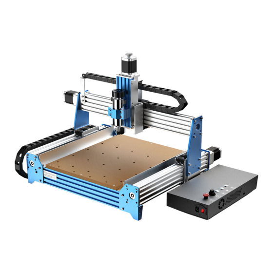
Machine Overview Designed for the PROVer XL 4030 V1/PROVer XL 6050 PLUS. Enable Rotary 3D or 2D Wrapped Engraving With Tailstock Length: 15-215mm Clamped Material Size Without Tailstock Length: 15-275mm Clamped Material Forward Mounting: 2-37mm Reverse Mounting: 20-67mm Diameter 5 installation positions, each position spacing is 20mm, and the range of adjustment is Tailstock Spacing Adjustment 20-80mm. -
Page 5: Rotary Module Dimensions
Rotary Module Dimensions Maximum Material Diameter of the Chuck: 37mm Base Plate Width: 125mm Total Length: 470mm The Longest Clamping Material: 215mm Tailstock Center Chuck Tailstock Engraving Machine Table from Material Rotation the Highest Center from Point: 105mm Engraving Machine Table: 60mm Base Plate Length: 400mm... -
Page 6: Package List
Package List Allen Wrench Rotary Module (2) Chuck Locking Wrench 4mm, 3mm 取 扱 説 明 書 English Rotary Module Kit for PROVer XL 4030 V1/PROVer XL 6050 PLUS 01 - 23 Drehmodul-Kit für PROVer XL 4030 V1/PROVer XL 6050 PLUS Deutsch 30 - 57 PROVer XL 4030 V1/PROVer XL 6050 PLUS用ロータリー... -
Page 7: Step
STEP 1 Install the Rotary Module on a 4030 or 6050 Machine 1. Align the holes in the rotary axis base plate with the holes in the machine's machining platform as shown in the figures. 2. Pre-lock the screws by screwing them through the over-holes in the base plate, and do not lock them for successful subsequent installation. - Page 8 STEP 1 Install the Rotary Module on a 4030 or 6050 Machine C. 6060 Aluminum with MDF Hybrid Platform D. 6050 Original Platform (Fixed with 8 M6x22 rounded hex screws with M6 slider nuts) (Fixed with 6 M6x18 rounded hex screws with M6 slider nuts)
- Page 9 STEP 2 Equipment X-axis Position Adjustment (Take 4030 for example) Rotary engraving requires the module to be as parallel as possible to your X-axis movement. When the rotation axis is not parallel to the direction of X-axis movement, it will lead to damage to the machine or a large error in the size of the engraved parts. To position/calibrate module alignment, the unit has 2 raised precision surfaces along the center of the module baseplate between the chuck and tailstock positions.
- Page 10 STEP 2 Equipment X-axis Position Adjustment (Take 4030 for example) Method 1: (Requires a Dial Test Indicator) 1. Attach the dial test indicator onto the Spindle mount base. 2. Jog the Spindle/indicator to Point A. Low the indicator so that the tip touches the side of the precision rail tab (A reading of 0.1mm on the dial test indicator is what you are looking for).
- Page 11 STEP 2 Equipment X-axis Position Adjustment (Take 4030 for example) Method 2: (Requires Round Pin Probe) This method relies more on experience and “feel” to align your Rotary module. 1. Replace the tool on the spindle with a precision round pin of the same diameter. 2.
- Page 12 STEP 2 Equipment X-axis Position Adjustment (Take 4030 for example) Figure showing the parallelism of the rotary axis with the X-axis of the device, please make sure that the two parts in the red box remain parallel.
- Page 13 STEP 3 Equipment Y-axis Position Adjustment (Take 4030 for example) Use the computer or offline, move the Y-axis of the device and align the center point of the device spindle with the midline of the rotary axis as shown in the figure. Top View Right View...
- Page 14 STEP 4 Wiring Disconned both of the Y-axis cables from the machine. Connect one of the cables to the Rotary Module and the other end to the Y-axis interface of the CNC engraver controller box.
-
Page 15: Step
STEP 5.1 Adjusting Rotary Chuck / Installing Material Stock 1. Insert the 2 locking wrenches into the chuck. 2. Hold one wrench still with one hand and turn the other wrench to adjust the jaws of the chuck to open or lock. Holding... -
Page 16: Step
STEP 5.2 Adjust the Tailstock 1. The tailstock can be used as needed depending on the engraving requirements. (The maximum loading length is 215mm when the tailstock is installed; without the tailstock, the maximum loading length increases to 275mm.) 2. Move to the proper location and tighten the four screws securing the tailstock spacing. 215mm 275mm... -
Page 17: Step
STEP 5.3 Adjust the Tailstock Insert the stock to be engraved, adjust the axis of the stock and the center of rotation of the rotary module in a line, then lock the chuck. Holding... -
Page 18: Step
STEP 5.4 Adjusting the Length of the Tailstock Spacing 1. Using the tailstock reduces possible wobble during operation of the clamped engraving material. 2. Rotate the handwheel to control the distance of the telescopic tailstock, as shown in the figure. 3. -
Page 19: Step
STEP 6 Prepare for Engraving 6.1 Blanks & Prep 1. Select the appropriate stock size as needed for your machined part. machined part size should be larger and bigger than stock size. 2. Setting the zero point of a machined part at the top of the end of the part. (The zero point of the machined part can be set according to your needs.) Engraving Stock Piece... - Page 20 STEP 6 Prepare for Engraving 6.2 Y-axis Tool Setting Operation According to the above installation steps, determine whether the center point of the main axis of the equipment is aligned with the midline of the rotary axis in the Y-axis direction, as shown in the figure.
- Page 21 STEP 6 Prepare for Engraving 6.3 Z-axis Tool Setting Operation 1. Attach the Z-probe kit, then place the Z-probe kit on the upper surface of the stock and perform tool setting operation. 2. When the tool bit just touches the upper surface of the stock as shown in the figure, the Z-axis tool setting is completed. Tool...
- Page 22 STEP 6 Prepare for Engraving 6.3 X-axis Tool Setting Operation 1. Move the X-axis so that the tool is in contact with the free end of the stock. 2. Zero the X coordinate, the position o is now the zero point of X-axis. Tool...
- Page 23 STEP 7 Adjustment of the Software Parameter In order for the rotary module to operate smoothly, the value of max travel for the Y-axis needs to be changed to 9999. So first of all we enter $131=9999. 7.1 Formula for Modifying Parameters $101=200 x Drive Subdivision x Rotational Speed Conversion/(Circumference) $101=200 x Drive Subdivision x Rotational Speed Conversion/(Diameter x π) Please calculate the pulse equivalent based on the actual measured stock diameter.
- Page 24 STEP 7 Adjustment of the Software Parameter 7.2 Input Parameter 1. First enter $$ to check the current value of parameter $101.
- Page 25 STEP 7 Adjustment of the Software Parameter 2. Enter “$101 = The value calculated according to the above formula”. 3. Enter $$ again to check whether the data is a successful input.
- Page 26 STEP 7 Adjustment of the Software Parameter 4. Modify the finished $ 101 parameter should be the value you entered, as shown below. Tool setting is completed, parameter modification is completed, you can start engraving! Wish you enjoy the fun of engraving with the rotary module!
- Page 27 Vielen Dank, dass Sie das Genmitsu Rotary Module Kit von SainSmart gekauft haben. Für technische Unterstützung senden Sie uns bitte eine E-Mail an support@sainsmart.com. Hilfe und Unterstützung finden Sie auch in unserer Facebook-Gruppe. (SainSmart Genmitsu CNC Users Group) Scannen Sie den QR-Code, um der Gruppe beizutreten und die Informationen zu finden.
- Page 28 Inhalt Überblick über die Maschine Abmessungen des Drehmoduls Liste der Pakete SCHRITT 1 SCHRITT 2 SCHRITT 3 SCHRITT 4 SCHRITT 5 SCHRITT 6 SCHRITT 7...
-
Page 29: Überblick Über Die Maschine
Überblick über die Maschine Entwickelt für den PROVer XL 4030 V1/PROVer XL 6050 PLUS. Ermöglicht Verwenden Sie rotierende 3D- oder 2D-Verpackungsgravur Mit Reitstock Länge: 15-215mm Geklemmtes Material Größe Ohne Reitstock Länge: 15-275mm Vorwärtsmontage: 2-37mm Eingespanntes Material Durchmesser Umgekehrte Montage: 20-67mm 5 Installationspositionen, jede Position hat einen Abstand von 20mm, und der Einstellung des Reitstockabstands Einstellbereich beträgt 20-80mm. -
Page 30: Abmessungen Des Drehmoduls
Abmessungen des Drehmoduls Maximaler Materialdurch- messer des Futters: 37mm Breite der Grundplatte: 125 mm Gesamtlänge: 470 mm Reitstock Das längste Einspannmaterial: 215mm Zentrum Chuck Reitstock Graviermaschi- nentisch vom höchsten Material Rotationsz- Punkt aus: entrum vom Gravier- 105mm maschinentisch: 60mm Länge der Grundplatte: 400 mm... -
Page 31: Liste Der Pakete
Liste der Pakete (2) Spannzangen Inbusschlüssel Drehbares Modul Verriegelungsschlüssel 4mm, 3mm 取 扱 説 明 書 English Rotary Module Kit for PROVer XL 4030 V1/PROVer XL 6050 PLUS 01 - 23 Abgerundete Drehmodul-Kit für PROVer XL 4030 V1/PROVer XL 6050 PLUS Deutsch 30 - 57 PROVer XL 4030 V1/PROVer XL 6050 PLUS用ロータリー... -
Page 32: Schritt
SCHRITT 1 Installieren Sie das Drehmodul an einer Maschine 4030 oder 6050 1. Richten Sie die Bohrungen in der Grundplatte der Drehachse mit den Bohrungen in der Bearbeitungsplattform der Maschine aus, wie in den Abbildungen gezeigt. 2. Sichern Sie die Schrauben vor, indem Sie sie durch die Überlöcher in der Grundplatte schrauben, und sichern Sie sie nicht für eine erfolgreiche spätere Installation. - Page 33 SCHRITT 1 Installieren Sie das Drehmodul an einer Maschine 4030 oder 6050 C. 6060 Aluminium mit MDF-Hybridplattform D. 6050 Original-Plattform (Befestigung mit 6 abgerundeten (Befestigung mit 8 abgerundeten Sechskantschrauben Sechskantschrauben M6x18 mit Gleitmuttern M6) M6x22 mit Gleitmuttern M6)
- Page 34 SCHRITT 2 Einstellung der Position der X-Achse (Beispiel: 4030) Bei der Rotationsgravur muss das Modul so parallel wie möglich zur Bewegung der X-Achse ausgerichtet sein. Wenn die Rotationsachse nicht parallel zur Bewegungsrichtung der X-Achse verläuft, führt dies zu einer Beschädigung der Maschine oder zu einem großen Fehler in der Größe der gravierten Teile.
- Page 35 SCHRITT 2 Einstellung der Position der X-Achse (Beispiel: 4030) Methode 1: (Erfordert eine Messuhr) 1. Befestigen Sie die Messuhr an der Spindelhalterung. 2. Bewegen Sie die Spindel/Anzeige auf Punkt A. Senken Sie die Anzeige so weit ab, dass die Spitze die Seite der Präzisionsschienenlasche berührt (ein Wert von 0,1 mm auf der Messuhr ist das, was Sie suchen).
- Page 36 SCHRITT 2 Einstellung der Position der X-Achse (Beispiel: 4030) Methode 2: (Erfordert runde Stiftsonde) Diese Methode beruht mehr auf Erfahrung und "Gefühl", um Ihr Rotary-Modul auszurichten. 1. Ersetzen Sie das Werkzeug auf der Spindel durch einen runden Präzisionsstift mit demselben Durchmesser. 2.
- Page 37 SCHRITT 2 Einstellung der Position der X-Achse (Beispiel: 4030) Die Abbildung zeigt die Parallelität der Drehachse mit der X-Achse des Geräts. Achten Sie bitte darauf, dass die beiden Teile im roten Kasten parallel bleiben.
- Page 38 SCHRITT 3 Einstellung der Position der Y-Achse des Geräts (z.B. 4030) Bewegen Sie die Y-Achse des Geräts am Computer oder offline und richten Sie den Mittelpunkt der Gerätespindel an der Mittellinie der Drehachse aus, wie in der Abbildung gezeigt. Ansicht von oben Rechte Ansicht...
- Page 39 SCHRITT 4 Verkabelung Lösen Sie die beiden Y-Achsenkabel von der Maschine. Verbinden Sie eines der Kabel mit dem Drehmodul und das andere Ende mit der Y-Achsen-Schnittstelle der CNC-Gravursteuerungsbox.
-
Page 40: Schritt
SCHRITT 5.1 Einstellen des Drehfutters / Einsetzen des Materialbestands 1. Setzen Sie die 2 Sicherungsschlüssel in das Spannfutter ein. 2. Halten Sie einen Schlüssel mit einer Hand fest und drehen Sie den anderen Schlüssel, um die Backen des Spannfutters zum Öffnen oder Verriegeln einzustellen. -
Page 41: Schritt
SCHRITT 5.2 Einstellen des Reitstocks 1. Der Reitstock kann je nach den Anforderungen an die Gravur verwendet werden. (Die maximale Ladelänge beträgt 215 mm, wenn der Reitstock installiert ist; ohne den Reitstock erhöht sich die maximale Ladelänge auf 275 mm). 2. -
Page 42: Schritt
SCHRITT 5.3 Einstellen des Reitstocks Legen Sie das zu gravierende Material ein, stellen Sie die Achse des Materials und den Drehpunkt des Drehmoduls in einer Linie ein und verriegeln Sie dann das Futter. Halten... -
Page 43: Schritt
SCHRITT 5.4 Einstellen der Länge des Reitstockabstands 1. Durch die Verwendung des Reitstocks wird ein mögliches Taumeln während des Betriebs des eingespannten Graviermaterials reduziert. 2. Drehen Sie das Handrad, um den Abstand des Teleskop-Reitstocks zu steuern, wie in der Abbildung gezeigt. 3. - Page 44 SCHRITT 6 Vorbereiten der Gravur 6.1 Rohlinge und Vorbereitung 1. Wählen Sie die geeignete Rohteilgröße für Ihr bearbeitetes Teil. Die Größe des bearbeiteten Teils sollte größer als die Rohteilgröße sein. 2. Einstellen des Nullpunkts eines bearbeiteten Teils am oberen Ende des Teils (Der Nullpunkt des bearbeiteten Teils kann je nach Bedarf eingestellt werden).
- Page 45 SCHRITT 6 Vorbereiten der Gravur 6.2 Y-Achse Werkzeugeinstellung Stellen Sie anhand der oben beschriebenen Installationsschritte fest, ob der Mittelpunkt der Hauptachse des Geräts mit der Mittellinie der Drehachse in Richtung der Y-Achse ausgerichtet ist, wie in der Abbildung dargestellt.
- Page 46 SCHRITT 6 Vorbereiten der Gravur 6.3 Einstellung des Z-Achsen-Werkzeugs 1. Bringen Sie den Z-Taster-Satz an, setzen Sie den Z-Taster-Satz auf die Oberseite des Werkstücks und führen Sie die Werkzeugeinstellung durch. 2. Wenn die Werkzeugschneide, wie in der Abbildung gezeigt, die Oberseite des Materials gerade berührt, ist die Einstellung des Z-Achsen-Werkzeugs abgeschlossen.
- Page 47 SCHRITT 6 Vorbereiten der Gravur 6.3 X-Achse Werkzeugeinstellung 1. Bewegen Sie die X-Achse so, dass das Werkzeug mit dem freien Ende des Werkstücks in Kontakt ist. 2. Nullen Sie die X-Koordinate, die Position o ist nun der Nullpunkt der X-Achse. Werkzeug...
-
Page 48: Schritt
SCHRITT 7 Einstellen der Softwareparameter Damit das Drehmodul reibungslos funktioniert, muss der Wert des maximalen Verfahrwegs für die Y-Achse auf 9999 geändert werden. Wir geben also zunächst $131=9999 ein. 7.1 Formel für die Änderung von Parametern $101=200 x Unterteilung des Antriebs x Umrechnung der Drehzahl/(Umfang) $101=200 x Unterteilung des Antriebs x Umrechnung der Drehzahl/(Durchmesser x π) Bitte berechnen Sie das Impulsäquivalent auf der Grundlage des tatsächlich gemessenen Schaftdurchmessers. - Page 49 SCHRITT 7 Einstellen der Softwareparameter 7.2 Eingabeparameter 1. Geben Sie zunächst $$ ein, um den aktuellen Wert des Parameters $101 zu überprüfen.
- Page 50 SCHRITT 7 Einstellen der Softwareparameter 2. Geben Sie "$101 = Der nach der obigen Formel berechnete Wert" ein. 3. Geben Sie erneut $$ ein, um zu prüfen, ob die Daten erfolgreich eingegeben wurden.
- Page 51 SCHRITT 7 Einstellen der Softwareparameter 4. Ändern Sie den fertigen $ 101 Parameter sollte der Wert sein, den Sie eingegeben haben, wie unten gezeigt. Die Werkzeugeinstellung ist abgeschlossen, die Parameteränderung ist abgeschlossen, Sie können mit der Gravur beginnen! Wir wünschen Ihnen viel Spaß beim Gravieren mit dem Drehmodul!
- Page 52 ようこそ このたびは玄光ロータリーモジュールキットをお買い上げいただき、誠にありがとうございます。 テクニカルサポートについては、support@sainsmart.com まで電子メールでお問い合わせください。 ヘルプとサポートはFacebookグループからもご利用いただけます。(サインスマート玄光CNCユーザーグループ) QRコードをスキャンしてグループに参加し、情報を見つける。 スキャンして探す CNC 資料 QRコードをスキャン してグループに参加 します...
- Page 53 目次 マシン概要 ロータリー・モジュールの寸法 パッケージ一覧 ステップ 1 ステップ 2 ステップ 3 ステップ 4 ステップ 5 ステップ 6 ステップ 7...
- Page 54 マシン概要 PROVer XL 4030 V1/PROVer XL 6050 PLUS 用に設計されています。回転式3Dまたは 用途 2Dラップ彫刻が可能 テールストック付き 長さ:15-215mm クランプ サイズ テールストックなし 長さ:15-275mm フォワード・マウント: 2-37mm クランプ径 リバースマウント:20-67mm テールストック間隔調整 5つの取り付け位置、各位置間隔は20mm、調整範囲は20-80mm。 芯金調整範囲 0-30mm 電気モーター NEMA23プラネタリギア式ステッピングモータ 101ドル=200×8×10/(直径×π) パルス等価 形状 サイズ 470×125×105mm(18.50インチ×4.92インチ×4.13インチ) 最高回転速度 480°/S 一方向最大回転角度 33512 x 360° 彫刻機テーブルからの回転軸の距離 60mm ロータリーモジュールの使用: 高精度を必要とするワークフローでは、ロータリーの初期セットアップとキャリブレーションが難しい場合があります。3D彫 刻やハイブリッド2D方式など、ロータリーを使った作業にはさまざまなオプションがあります。使用するソフトウェアによっ て、各手法には異なるワークフローがあります。問題が発生した場合は、遠慮なくフェイスブックのグループに参加して助けを 求めたり、カスタマーサービスにご相談ください。...
- Page 55 ロータリー・モジュールの寸法 チャックの最大素材直径: 37mm ベースプレート幅:125mm 全長:470mm テールストックセンター 最も長いクランプ素材:215mm チャック テールス トック 一番高いとこ ろからの彫刻 機テーブル: 彫刻機テーブルから 105mm の材料回転中心: 60mm ベースプレートの長さ:400mm...
- Page 56 パッケージ一覧 六角レンチ ロータリーモジュール (2) チャックロックレンチ 4mm, 3mm 取 扱 説 明 書 Rotary Module Kit for PROVer XL 4030 V1/PROVer XL 6050 PLUS English 01 - 23 Drehmodul-Kit für PROVer XL 4030 V1/PROVer XL 6050 PLUS Deutsch 30 - 57 PROVer XL 4030 V1/PROVer XL 6050 PLUS用ロータリー ・ モジュール ・ キッ ト 日 本 語 59 - 86 V1.0 Mar 2024 六角丸ネジ ユーザーマ (9) M6 x 18 (9) M6 Tスロットナット ニュアル (9) M6 x 22...
- Page 57 ステップ 1 4030 または 6050 マシンへのロータリー・モジュールの取り付け 1. 回転軸ベースプレートの穴と機械の加工台の穴を図のように合わせます。 2. ベースプレートのオーバーホールにネジをねじ込み、あらかじめロックしておきます。 ヒント:異なる機器と異なるプラットフォームプレートは、異なる穴位置に対応して、次の図に従って、あなたのマシンの穴位 置を決定してください。 A. 4030 V1 オリジナルMDFプラットフォーム B. 4030アルミニウム・プラットフォーム (M6x22丸六角ネジ6本で固定) (M6x18丸六角ネジ8本とM6スライダーナットで固定)...
- Page 58 ステップ 1 4030 または 6050 マシンへのロータリー・モジュールの取り付け C. 6060アルミニウムとMDFのハイブリッド・プラッ D. 6050オリジナル・プラットフォーム トフォーム (M6×22丸六角ネジ8本とM6スライダーナットで固定) (M6x18丸六角ネジ6本とM6スライダーナットで固定)...
- Page 59 ステップ 2 装置の X 軸位置調整(4030 を例とする) ロータリー彫刻では、モジュールをX軸の動きとできるだけ平行にする必要があります。回転軸がX軸の移動方向と平行でない場 合、機械の破損や彫刻部品のサイズに大きな誤差が生じます。 モジュールのアライメントを位置決め/較正するために、このユニットには、チャックとテールストックの位置の間に、モジュー ルのベースプレートの中央に沿った2つの隆起した精密面があります。(テールストックを取り外すとキャリブレーションが容易 になります。) X軸の移動方向 精密サーフェス タブ 回転軸 注:A点はチャックに近い方を、B点はチャックから最も遠い方を示す。精密面とは、上図の昇降レールのこと。...
- Page 60 ステップ 2 装置の X 軸位置調整(4030 を例とする) 方法1:(ダイヤルテストインジケーターが必要) 1. ダイヤルテストインジケータをスピンドルマウントベースに取り付けます。 2. スピンドル/インジケータをポイントAまでジョグします。先端が精密レール・タブの側面に触れるようにインジケータを下げ ます(ダイヤルテスト・インジケータで0.1mmを読み取ります)。次に、ダイヤルテストインジケーターをゼロに設定します。 3. マシンをゆっくりとB点に向けてジョグし、インジケータを見ながらB点に到達したときの読み取り値を確認します。読み取り値 が0のままであれば、アライメント校正は完了です。 4. 読み取り値が0でない場合は、モジュールのベースプレートの位置を微調整し、読み取り値が0になるまで上記の手順を繰り返し ます。 5. 較正後、モジュールのベースプレートのネジを締めます。 精密サーフェス...
- Page 61 ステップ 2 装置の X 軸位置調整(4030 を例とする) 方法2:(ラウンドピンプローブが必要)この方法は、ロータリーのモジュールをアライメントするために、より経験と「感覚」 に頼ることになります。 1. スピンドルの工具を、同じ直径の精密丸ピンに交換する。 2. 2点間の距離は約140mm。 3. 主軸上の丸ピンがタブの精密面に接触するように、マシンをジョグしてA点にゆっくりと近づけます。 4. 上図のように、B点で丸ピンとタブの精密面が接触するように、ロータリーモジュールの平行アライメントを調整する。 5. 上記のステップを繰り返し、B点でぴったり合うまで何度も調整する。 6. アライメントが完了したら、モジュールのベースプレートを締めます。 丸ピン 精密サーフェス...
- Page 62 ステップ 2 装置の X 軸位置調整(4030 を例とする) 回転軸と装置のX軸の平行度を示す図。赤枠内の2つの部品が平行のままであることを確認してください。...
- Page 63 ステップ 3 装置のY軸位置調整(4030を例とする) コンピューターまたはオフラインで、装置のY軸を動かし、図のように装置のスピンドルの中心点を回転軸の正中線に合わせる。 トップビュー 右の眺め...
- Page 64 ステップ 4 配線 機械から両方のY軸ケーブルを切り離す。ケーブルの一方をロータリーモジュールに接続し、もう一方をCNC彫刻機のコントロ ーラーボックスのY軸インターフェースに接続します。...
- Page 65 ステップ 5.1 回転チャックの調整/材料ストックの取り付け 1. ロッキングレンチ2本をチャックに挿入する。 2. 片方のレンチを片手で静止させ、もう片方のレンチを回して、チャックのジョーの開閉を調整する。 ホールディング...
- Page 66 ステップ 5.2 テールストックの調整 1. テールストックは、彫刻の必要性に応じて使用することができます。(テールストック装着時の最大積載長は215mm、テールス トック無しの場合は275mmになります) 2. 適切な位置に移動し、テールストックの間隔を固定している4本のネジを締めます。 215mm 275mm...
- Page 67 ステップ 5.3 テールストックの調整 彫刻するストックを挿入し、ストックの軸とロータリーモジュールの回転中心が一直線になるように調整し、チャックをロック します。 ホールディング...
- Page 68 ステップ 5.4 テールストックスペーシングの長さ調整 1. テールストックを使用することで、クランプされた彫刻材料の操作中に起こりうるぐらつきを軽減します。 2. 図のように、ハンドホイールを回してテレスコピック芯押台の距離を調節します。 3. テールストックが彫刻材料の自由端に接触したら、サイドハンドルを回してテールストックを固定します。 フリー・エンド ハンドホイール...
- Page 69 ステップ 6 彫刻の準備 6.1 ブランクとプレパレーション 1. 機械加工部品のサイズは、ストックサイズよりも大きくする必要があります。 2. 機械加工部品のゼロ点を部品端の上部に設定する(機械加工部品のゼロ点はニーズに応じて設定できる)。 エングレービング・パ ート・ゼロ・ポイント ストック・ピース...
- Page 70 ステップ 6 彫刻の準備 6.2 Y軸工具設定操作 上記の設置手順に従い、図のように装置の主軸の中心点がY軸方向の回転軸の正中線と一致しているかどうかを判断する。...
- Page 71 ステップ 6 彫刻の準備 6.3 Z軸工具設定操作 1. Zプローブキットを取り付け、Zプローブキットをストック上面に置き、ツールセッティング作業を行う。 2. 図に示すように、工具ビットがストックの上面にちょうど接触したら、Z軸工具のセッティングは完了です。 工具 ...
- Page 72 ステップ 6 彫刻の準備 6.3 X軸ツール設定操作 1. 工具がストックの自由端に接触するようにX軸を動かす。 2. X座標をゼロにすると、位置oはX軸のゼロ点になる。 工具...
- Page 73 ステップ 7 ソフトウェアパラメータの調整 ロータリーモジュールをスムーズに動作させるためには、Y軸の最大トラベルの値を9999に変更する必要がある。そこで、まず $131=9999と入力する。 7.1 パラメーターの修正式 101ドル=200×駆動分担×回転数換算/(円周率) 101ドル=200×駆動分担×回転数換算/(直径×π) 実測の純正径からパルス換算してください。 A. 6050用 ドライブ細分化: 8 回転数換算:10 直径 30cmの円筒形のレリーフを例にして、計算 式を考えてみよう: 円周率 $101=200x8x10/(30xπ)=169.851 B. 4030用 ドライブ細分化: 8 回転数換算:10 30cmの円筒形のレリーフを例にして、計算 式を考えてみよう: $101=200x8x10/(30xπ)=169.851...
- Page 74 ステップ 7 ソフトウェアパラメータの調整 7.2 入力パラメータ 1. まず$$を入力し、パラメーター$101の現在値をチェックする。...
- Page 75 ステップ 7 ソフトウェアパラメータの調整 2. 101ドル=上記の計算式に従って算出された値」と入力する。 3. もう一度$を入力し、データが正常に入力されたかどうかを確認する。 ...
- Page 76 ステップ 7 ソフトウェアパラメータの調整 4. 完成した$ 101パラメータを以下のように入力した値に修正する。 工具のセッティングが完了し、パラメーターの変更が完了したら、彫刻を開始することができます!ロータリーモジュールで彫 刻の楽しさを味わってください!...
- Page 77 Genmitsu Desktop CNC & Laser Email: support@sainsmart.com Facebook messenger: https://m.me/SainSmart Help and support is also available from our Facebook Group Vastmind LLC, 5892 Losee Rd Ste. 132, N. Las Vegas, NV 89081 Facebook Group...
Need help?
Do you have a question about the Genmitsu and is the answer not in the manual?
Questions and answers