Advertisement
Table of Contents
Advertisement
Table of Contents

Related Manuals for Technoflux Micro Welder Power

Summary of Contents for Technoflux Micro Welder Power
- Page 1 Ref. SOP0P0005 User Manual Micro Welder Power...
- Page 3 INDEX 1. INTRODUCTION 2. WARRANTY 3. TECHNICAL SPECIFICATIONS 4. PRESENTATION 5. DISPLAYS 6. START-UP 7. STOPPING THE MACHINE 8. WELD 9. SAVE PARAMETERS 10. CAMERA AND SCREEN 11. MAINTENANCE 12. SECURITY...
-
Page 4: Warranty
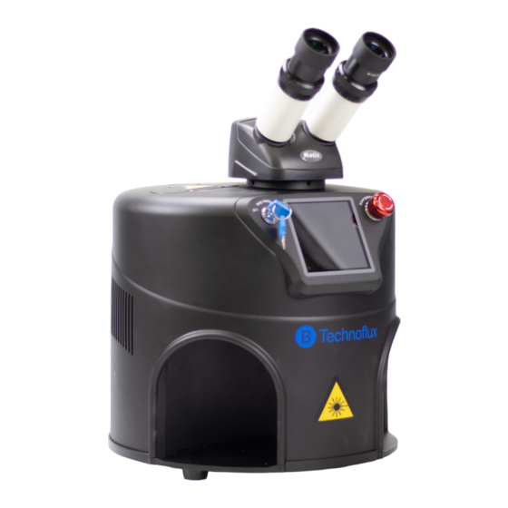
Read this manual carefully and in case of doubt contact the technical service. 2. Warranty TECHNOFLUX products are covered by a twelve-month warranty from the date of delivery to the customer. Misuse of the unit voids this warranty. 3. Technical specifications... - Page 5 4. Presentation Microscope. Ignition key. Emergency stop Screen. Welding chamber Pedal connection Ventilation Network input 5. Screens Start Screen In the upper bar we have three symbols that when pressed activate screens and functions 1. Settings key 2. Screen key 3.
- Page 6 Settings screen description. This screen contains the internal Software control settings, some of which are factory predetermined. Which can only be accessed by technical service. To exit the numerical screen press “Back” 6. Start up 1. Place the machine on a flat, firm surface and in a dust-free environment, leave 40 cm on both sides of the machine: This distance is very important for proper cooling of the laser welder.
-
Page 7: Machine Stop
8. After the initial screen appears the home screen. 9. On this home screen there are two messages in red indicating lamp off and refrigeration system off. In the upper right corner we can see the power symbol. 10. Press the power symbol, a countdown from 9 to 1 begins, at the end the machine is automatically activated and the two messages in red enter On. - Page 8 3th - To weld it is necessary to apply different parameters depending on the metal to be welded. These parameters can be saved by means of the numerical memory of the machine. Next we attach a dial with the initial parameters for the most common metals and in section 8 how to save the parameters in the memory.
-
Page 9: Maintenance
11. Maintenance. It is necessary to keep the optical elements clean, both optics of the microscope and the objec- tive located in the welding chamber. Use chamois to clean glasses. Visually check the protection filter of the welding objective, if it is damaged, replace it according to the instructions of the technical service. - Page 10 Benmayor S.A. A-60512100 Bach, 2-B. Pol. Ind. Foinvasa 08110 Montcada i Reixac, Barcelona benmayor@benmayor.com T +34 935 724 161 / F +34 935 724 165 www.benmayor.com...
Need help?
Do you have a question about the Micro Welder Power and is the answer not in the manual?
Questions and answers