Table of Contents
Advertisement
Quick Links
RT9490WSC
Evaluation Board
5A 2-4 Cell Buck-Boost Switching Battery Charger
Evaluation Board
General Description
The Evaluation Board demonstrates that the RT9490WSC is designed for a highly-integrated 5A Buck-Boost switch
mode battery charge management and system power path management device for 2-4 cell Li-Ion and Li-polymer
batteries. The low impedance power path optimizes switch-mode operation efficiency, reduces battery charging time,
2
and extends battery life during the discharging phase. The I
C serial interface with charging and system settings
makes the device a truly flexible solution.
Table of Contents
General Description ...................................................................................................................................................... 1
Performance Specification Summary ........................................................................................................................... 2
Detailed Description of Hardware ................................................................................................................................. 3
Quick Start Procedure .................................................................................................................................................. 6
Evaluation GUI Software Tool Installation and Introduction ......................................................................................... 8
Test Procedure ............................................................................................................................................................ 12
Typical Applications .................................................................................................................................................... 22
Bill of Materials............................................................................................................................................................ 23
Evaluation Board Layout ............................................................................................................................................. 25
More Information ......................................................................................................................................................... 29
Important Notice for Richtek Evaluation Board ........................................................................................................... 29
EVB_RT9490WSC-01
April 2024
1
http://www.richtek.com
Advertisement
Table of Contents

Related Manuals for Richtek RT9490WSC


Summary of Contents for Richtek RT9490WSC
-
Page 1: Table Of Contents
Evaluation Board General Description The Evaluation Board demonstrates that the RT9490WSC is designed for a highly-integrated 5A Buck-Boost switch mode battery charge management and system power path management device for 2-4 cell Li-Ion and Li-polymer batteries. The low impedance power path optimizes switch-mode operation efficiency, reduces battery charging time, and extends battery life during the discharging phase. -
Page 2: Performance Specification Summary
RT9490WSC Evaluation Board Performance Specification Summary Summary of the RT9490WSC Evaluation Board performance specification is provided in Table 1. The ambient temperature is 25°C. Table 1. RT9490WSC Evaluation Board Performance Specification Summary Specification Test Conditions Unit Supply Input Voltage Range... -
Page 3: Detailed Description Of Hardware
RT9490WSC Evaluation Board Detailed Description of Hardware Headers Description and Placement Carefully inspect all the components used in the EVB according to the following Bill of Materials table, and then make sure all the components are undamaged and correctly installed. If there is any missing or damaged component, which may occur during transportation, please contact our distributors or e-mail us at evb_service@richtek.com. - Page 4 RT9490WSC Evaluation Board Test Points The EVB is provided with the test points and pin names listed in the table below. Test Point/ Function Pin Name VIN1 Input voltage for VAC1. PGND Ground. VIN2 Input voltage for VAC2. SYSTEM Output voltage for sys.
- Page 5 RT9490WSC Evaluation Board Test Point/ Function Pin Name JP40 PROG resistence jumper for default set 3S_750KHz_1A ICHG. JP41 PROG resistence jumper for default set 4S_1.5MHz_1A ICHG. JP42 PROG resistence jumper for default set 4S_750KHz_1A ICHG. VAC1-VBUS short pad. VAC2-VBUS short pad.
-
Page 6: Quick Start Procedure
RT9490WSC Evaluation Board Quick Start Procedure Suggestion Required Equipments RT9490WSC Evaluation Board ⚫ DC power supply capable of 24V, 3.3A ⚫ Battery simulator capable of 18.8V, 10A ⚫ Electronic load capable of 10A ⚫ Oscilloscope ⚫ Evaluation Board Jumper Setup The Evaluation Board is fully assembled and tested. - Page 7 4. Use I C to set registers for charging function and proper protection level. Richtek also provides designers GUI software tool to read or write registers. The details are shown in the next chapter ” Evaluation GUI Software Tool Installation and Introduction”.
-
Page 8: Evaluation Gui Software Tool Installation And Introduction
Follow the below steps to install the relative software tools. 1. Richtek Bridgeboard Utilities Installation Get the Richtek Bridgeboard Utilities, user manual and purchase the bridge board from the website. https://www.richtek.com/Design%20Support/Reference%20Design/RD0001-01?sc_lang=en Please follow the user manual to install the Richtek Bridgeboard Utilities. - Page 9 RT9490WSC Evaluation Board 3. The introduction of GUI interface is as below. All registers can be read/written in these pages. You can select which byte you want to read/write in this column. The selected register will continue to be read after click the scan button.
- Page 10 RT9490WSC Evaluation Board This page is for charging behavior setting. This type of dropdown menu allows you to select the setting you need. You can scroll down/up to select the register setting. This type of menu allows you to select the bit setting you need. A solid fill indicates your selection.
- Page 11 RT9490WSC Evaluation Board Grey means 0 Red means 1 These lamp icon are STATUS type of register. EVB_RT9490WSC-01 April 2024 http://www.richtek.com...
-
Page 12: Test Procedure
Connect the Wrenboard to the computer GUI Setup 1. Follow the section” Evaluation GUI Software Tool Installation” to Install the GUI tool. 2. Connect Richtek Wrenboard to evaluation board through JP33 SCL/SDA/PGND pin. 3. Connect Richtek Wrenboard to the computer. EVB_RT9490WSC-01 April 2024 http://www.richtek.com... - Page 13 RT9490WSC Evaluation Board 4. After providing power to the Evaluation Board, run the RT9490_RT9490S_GUI_V4.exe. 5. If GUI connection is successful, the slave address ID will show 0x53. EVB_RT9490WSC-01 April 2024 http://www.richtek.com...
- Page 14 RT9490WSC Evaluation Board Register Initial Setting 1. For board evaluation, disable watchdog initially if don’t want to verify watchdog function. 2. Check whether BATTERY_CELL setting is the same as PROG pin setting. This register can also be changed after powered up.
- Page 15 RT9490WSC Evaluation Board 9. Check whether VAC_OVP level is large enough. It should bigger than VBUS input voltage. 10. The charger input current limit is decided by the minimum value between AICR and ILIM. If do not want to verify the ILIM_HZ function, disabled ILIM_HZ function.
- Page 16 RT9490WSC Evaluation Board 2. Check whether it triggers AICR_STAT, MIVR_STAT, or other protections. 3. If it triggers AICR_STAT, it means that the input current is near limitation level. Increase input voltage or reduce ICHG_CTRL setting to leave AICR_STAT. 4. If it triggers MIVR_STAT, it means that the input power is not enough and input source voltage drops. Increase input power ability or reduce ICHG_CTRL setting to leave MIVR_STAT.
- Page 17 RT9490WSC Evaluation Board 9. Check that CHG_STAT is into CV mode. 10. Continue increasing the battery voltage. Check that the BAT charging current is gradually down in CV mode. 11. After BAT charging current is below IEOC level, the RT9490 will stop charging.
- Page 18 RT9490WSC Evaluation Board 3. Set the OTG voltage level. 4. Enable EN_OTG. The RT9490 will start to output voltage at the VBUS pin. 5. On the RT9490 evaluation board, there are mounted AC-RBFETs already. If AC-RBFET is used by jumper setting(see the details in the section”...
- Page 19 RT9490WSC Evaluation Board 7. After OTG starts, OTG voltage is still able to be set. EVB_RT9490WSC-01 April 2024 http://www.richtek.com...
- Page 20 RT9490WSC Evaluation Board Measure Results Reference Power Up with VAC Pluged in Charging in Buck Mode (5V/Div) (5V/Div) ACDRV1 (5V/Div) = 5V, V = 8V,DCP (5V/Div) Time (50ms/Div) Charging in Boost Mode Charging in Buck-Boost Mode (5V/Div) (5V/Div) (5V/Div) (2A/Div)
- Page 21 RT9490WSC Evaluation Board 1s Battery Charger Efficiency 2s Battery Charger Efficiency Charger Efficiency vs. Charge Current (1s Battery) = 5V = 9V = 15V = 20V = 4V, f = 1.5MHz, L = 1µH, LDCR = 6.7mΩ Charge Current (A)
-
Page 22: Typical Applications
RT9490WSC Evaluation Board Typical Applications EVB Schematic Diagram GATE_SOURCE IC_PMID BAT-BATTERY Shipping_MOS_D PULL_UP_I2C PULL_UP_INT PULL_UP_CE BATTERY SYSTEM GND4 GND2 RX1+ TX1+ RX1- TX1- Type_C_IN Type_C_IN VBUS4 VBUS2 PD_CC1 SBU2 PD_CC2 SBU1 Type_C_IN Type_C_IN VBUS3 VBUS1 TX2- RX2- TX2+ RX2+ GND3... -
Page 23: Bill Of Materials
RT9490WSC Evaluation Board Bill of Materials = 1.5MHz Reference Count Part Number Value Description Package Manufacturer WL-CSP-56B RT9490WSC Switching Charger RICHTEK 2.93x3.46 (BSC) Capacitor, Ceramic, C7, C18 GRM033R61C473KE84 47nF C-0201 MURATA 16V, X5R C10, C13, Capacitor, Ceramic, C22, C23, GRM188R6YA106MA73 10µF... - Page 24 RT9490WSC Evaluation Board = 1.5MHz Reference Count Part Number Value Description Package Manufacturer Resistor, Chip, WR06X1003FTL 100k R-0603 WALSIN 1/10W, 1% Resistor, Chip, WR06X3012FTL 30.1k R-0603 WALSIN 1/10W, 1% Resistor, Chip, RTT033001FTP R-0603 RALEC 1/10W, 1% Resistor, Chip, WR06X4701FTL 4.7k...
-
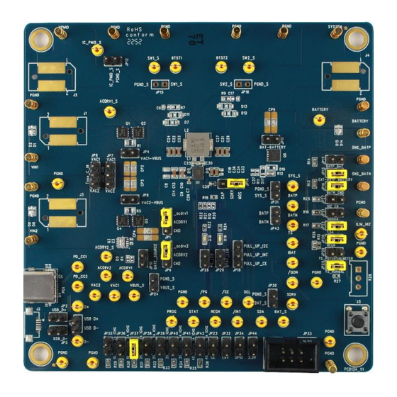
Page 25: Evaluation Board Layout
Evaluation Board Evaluation Board Layout Figure 1 to Figure 4 are RT9490WSC Evaluation Board layout. This board size is 101.6mm x 101.6mm and is constructed on four-layer PCB, outer layers with 1 oz. Cu and inner layers with 1 oz. Cu. - Page 26 RT9490WSC Evaluation Board Figure 2. PCB Layout—Inner Side (2 Layer) EVB_RT9490WSC-01 April 2024 http://www.richtek.com...
- Page 27 RT9490WSC Evaluation Board Figure 3. PCB Layout—Inner Side (3 Layer) EVB_RT9490WSC-01 April 2024 http://www.richtek.com...
- Page 28 RT9490WSC Evaluation Board Figure 4. Bottom View (4 Layer) EVB_RT9490WSC-01 April 2024 http://www.richtek.com...
-
Page 29: More Information
THIS DOCUMENT IS FOR REFERENCE ONLY, NOTHING CONTAINED IN THIS DOCUMENT SHALL BE CONSTRUED AS RICHTEK’S WARRANTY, EXPRESS OR IMPLIED, UNDER CONTRACT, TORT OR STATUTORY, WITH RESPECT TO THE PRESENTATION HEREIN. IN NO EVENT SHALL RICHTEK BE LIABLE TO BUYER OR USER FOR ANY AND ALL DAMAGES INCLUDING WITHOUT LIMITATION TO DIRECT, INDIRECT, SPECIAL, PUNITIVE OR CONSEQUENTIAL DAMAGES.
Need help?
Do you have a question about the RT9490WSC and is the answer not in the manual?
Questions and answers