Table of Contents
Advertisement
Quick Links
RT9492GQVF(2)
Evaluation Board
5A 2-4 Cell Buck-Boost Switching Battery Charger
Evaluation Board
General Description
The Evaluation Board demonstrates that the RT9492GQVF(2) is designed for a highly-integrated 5A Buck-Boost
switch mode battery charge management and system power path management device for 2-4 cell Li-Ion and Li-
polymer batteries. The low impedance power path optimizes switch-mode operation efficiency, reduces battery
2
charging time, and extends battery life during the discharging phase. The I
C serial interface with charging and system
settings makes the device a truly flexible solution.
Table of Contents
General Description ...................................................................................................................................................... 1
Performance Specification Summary ........................................................................................................................... 2
Detailed Description of Hardware ................................................................................................................................. 3
Quick Start Procedure .................................................................................................................................................. 6
Evaluation GUI Software Tool Installation and Introduction ......................................................................................... 8
Test Procedure ............................................................................................................................................................ 12
Typical Applications .................................................................................................................................................... 22
Bill of Materials............................................................................................................................................................ 23
Evaluation Board Layout ............................................................................................................................................. 25
More Information ......................................................................................................................................................... 29
Important Notice for Richtek Evaluation Board ........................................................................................................... 29
EVB_RT9492GQVF(2)-01
March 2024
1
http://www.richtek.com
Advertisement
Table of Contents

Related Manuals for Richtek RT9492GQVF(2)


Summary of Contents for Richtek RT9492GQVF(2)
-
Page 1: Table Of Contents
Evaluation GUI Software Tool Installation and Introduction ..................8 Test Procedure ................................12 Typical Applications ..............................22 Bill of Materials................................23 Evaluation Board Layout ............................. 25 More Information ................................. 29 Important Notice for Richtek Evaluation Board ......................29 EVB_RT9492GQVF(2)-01 March 2024 http://www.richtek.com... -
Page 2: Performance Specification Summary
Table 1. RT9492GQVF(2) Evaluation Board Performance Specification Summary Specification Test Conditions Unit Supply Input Voltage Range Maximum Input Current Maximum OTG Current OTG mode 3.32 Maximum Output Current (SW2), ISYS Maximum Battery Voltage 18.8 Maximum Charge Current Maximum Discharge Current EVB_RT9492GQVF(2)-01 March 2024 http://www.richtek.com... -
Page 3: Detailed Description Of Hardware
Carefully inspect all the components used in the EVB according to the following Bill of Materials table, and then make sure all the components are undamaged and correctly installed. If there is any missing or damaged component, which may occur during transportation, please contact our distributors or e-mail us at evb_service@richtek.com. EVB_RT9492GQVF(2)-01 March 2024... - Page 4 PROG resistence jumper for default set 4S_1.5MHz_1A ICHG. JP29 PROG resistence jumper for default set 4S_750KHz_1A ICHG. JP32 STAT_LED enable jumper. VAC1-VBUS short pad. VAC2-VBUS short pad. BAT-BATTERY short pad. Button for exit ship mode or system reset. EVB_RT9492GQVF(2)-01 March 2024 http://www.richtek.com...
- Page 5 Short ACDRV2 to _acdrv2. Short SDRV to MOS. Short BATP to BATTERY. JP12 Short REGN to TS pull-up resistor. JP18 Short TS to normal temperature resistor. JP14 Short ILIM for 1.5A. JP24 For 2 cell/1.5MHz setting. EVB_RT9492GQVF(2)-01 March 2024 http://www.richtek.com...
-
Page 6: Quick Start Procedure
Proper measurement equipment setup and follow the procedure below. 1. With power off, connect input power and ground to VIN1 or VIN2 and PGND respectively. 2. With load off, connect electronic load to SYSTEM and PGND respectively. EVB_RT9492GQVF(2)-01 March 2024 http://www.richtek.com... - Page 7 4. Use I C to set registers for charging function and proper protection level. Richtek also provides designers GUI software tool to read or write registers. The details are shown in the next chapter ” Evaluation GUI Software Tool Installation and Introduction”.
-
Page 8: Evaluation Gui Software Tool Installation And Introduction
Follow the below steps to install the relative software tools. 1. Richtek Bridgeboard Utilities Installation Get the Richtek Bridgeboard Utilities, user manual and purchase the bridge board from the website. https://www.richtek.com/Design%20Support/Reference%20Design/RD0001-01?sc_lang=en Please follow the user manual to install the Richtek Bridgeboard Utilities. - Page 9 The selected register will continue to be read after click the scan button. Write: The selected register will be written to the device after click the write button. Read: The selected register will be updated after click the read button. EVB_RT9492GQVF(2)-01 March 2024 http://www.richtek.com...
- Page 10 This type of dropdown menu allows you to select the setting you need. You can scroll down/up to select the register setting. This type of menu allows you to select the bit setting you need. A solid fill indicates your selection. EVB_RT9492GQVF(2)-01 March 2024 http://www.richtek.com...
- Page 11 RT9492GQVF(2) Evaluation Board Grey means 0 Red means 1 These lamp icon are STATUS type of register. EVB_RT9492GQVF(2)-01 March 2024 http://www.richtek.com...
-
Page 12: Test Procedure
Connect the Wrenboard to the computer GUI Setup 1. Follow the section” Evaluation GUI Software Tool Installation” to Install the GUI tool. 2. Connect Richtek Wrenboard to evaluation board through JP71 SCL/SDA/PGND pin. 3. Connect Richtek Wrenboard to the computer. EVB_RT9492GQVF(2)-01 March 2024 http://www.richtek.com... - Page 13 RT9492GQVF(2) Evaluation Board 4. After providing power to the Evaluation Board, run the RT9492_RT9492S_GUI_V1.exe. 5. If GUI connection is successful, the slave address ID will show 0x53. EVB_RT9492GQVF(2)-01 March 2024 http://www.richtek.com...
- Page 14 6. Set VMIVR for input voltage limitation level. Set it lower than test input voltage. 7. Set IAICR for input current limitation level. Set it lower than test input source current limit. 8. Set the IEOC for charging termination level. EVB_RT9492GQVF(2)-01 March 2024 http://www.richtek.com...
- Page 15 1. After finishing register initial setting, give VAC1 or VAC2 pin input power to start charger. For example, give it 15V. 5~20V VAC1 adapter input Multi-Cell Battery 0~18.8V 5~20V VAC2 adapter input WrenBoard Connect the Wrenboard to the computer EVB_RT9492GQVF(2)-01 March 2024 http://www.richtek.com...
- Page 16 8. Measure the charging current and the BATP pin voltage as the battery voltage increases. Once the charging current starts to fall down, verify that the voltage remains at the VBAT_REG level (IR drop + VBAT = VBAT_REG level). EVB_RT9492GQVF(2)-01 March 2024 http://www.richtek.com...
- Page 17 17. Plug out the VAC input power. RT9492 will stop charging. OTG Function Test 1. Finish register initial setting as section” Register initial setting” . 2. Make sure the battery voltage is above VOTG_LBP (typ. 2.7V). For example, provide it 8V. EVB_RT9492GQVF(2)-01 March 2024 http://www.richtek.com...
- Page 18 For example, if VAC1 RBFET is used, EN_ACDRV1 should be enabled. The RT9492 starts to output OTG voltage after register EN_ACDRV1 is set to 1. 6. Measure the VBUS pin and VAC pin to verify the OTG setting level. EVB_RT9492GQVF(2)-01 March 2024 http://www.richtek.com...
- Page 19 RT9492GQVF(2) Evaluation Board 7. After OTG starts, OTG voltage is still able to be set. EVB_RT9492GQVF(2)-01 March 2024 http://www.richtek.com...
- Page 20 RT9492GQVF(2) Evaluation Board Measure Results Reference Power-UP with AC_RB1, VAC1 Plug in Charging in Buck Mode Charging in Boost Mode Charging in Buck-Boost Mode EVB_RT9492GQVF(2)-01 March 2024 http://www.richtek.com...
- Page 21 Note: When measuring the input or output voltage ripple, care must be taken to avoid a long ground lead on the oscilloscope probe. Measure the output voltage ripple by touching the probe tip directly across the output capacitor. EVB_RT9492GQVF(2)-01 March 2024 http://www.richtek.com...
-
Page 22: Typical Applications
JP18 JP19 PGND GP19 PGND STAT_LED PGND JP32 STAT PGND PROG JP22 JP23 JP24 JP25 JP26 JP27 JP28 JP29 2S_1.5MHz_2A ICHG 4S_1.5MHz_1A ICHG 1S_1.5MHz_2A ICHG 1S_750KHz_2A ICHG 2S_750KHz_2A ICHG 3S_1.5MHz_1A ICHG 3S_750KHz_1A ICHG 4S_750KHz_1A ICHG PGND EVB_RT9492GQVF(2)-01 March 2024 http://www.richtek.com... -
Page 23: Bill Of Materials
RT9492GQVF(2) Evaluation Board Bill of Materials = 1.5MHz Reference Count Part Number Value Description Package Manufacturer VQFN-29TL 4x4 RT9492GQVF(2) Switching charger RICHTEK (FC) Capacitor, Ceramic, C6, C8 GRM033R61C473KE84 47nF C-0201 MURATA 16V, X5R Capacitor, Ceramic, C14, C15, 0402B104K500CT 0.1µF C-0402... - Page 24 Resistor, Chip, 10.5kΩ WR06X1052FTL R-0603 WALSIN 1/10W, 1% Resistor, Chip, 13.7kΩ WR06X1372FTL R-0603 WALSIN 1/10W, 1% Resistor, Chip, 17.4kΩ RTT031742FTP R-0603 RALEC 1/10W, 1% Resistor, Chip, 27kΩ CR0603F27K0P05Z R-0603 EVER OHMS 1/10W, 1% HTS6601H SW-TACT-SWITCH TACT-BTN High-Tronics EVB_RT9492GQVF(2)-01 March 2024 http://www.richtek.com...
-
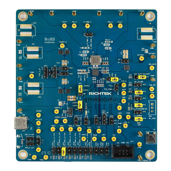
Page 25: Evaluation Board Layout
Figure 1 to Figure 4 are RT9492GQVF(2) Evaluation Board layout. This board size is 101.6mm x 109.7mm and is constructed on four-layer PCB, outer layers with 1 oz. Cu and inner layers with 1 oz. Cu. Figure 1. Top View (1 layer) EVB_RT9492GQVF(2)-01 March 2024 http://www.richtek.com... - Page 26 RT9492GQVF(2) Evaluation Board Figure 2. PCB Layout—Inner Side (2 Layer) EVB_RT9492GQVF(2)-01 March 2024 http://www.richtek.com...
- Page 27 RT9492GQVF(2) Evaluation Board Figure 3. PCB Layout—Inner Side (3 Layer) EVB_RT9492GQVF(2)-01 March 2024 http://www.richtek.com...
- Page 28 RT9492GQVF(2) Evaluation Board Figure 4. Bottom View (4 Layer) EVB_RT9492GQVF(2)-01 March 2024 http://www.richtek.com...
-
Page 29: More Information
THIS DOCUMENT IS FOR REFERENCE ONLY, NOTHING CONTAINED IN THIS DOCUMENT SHALL BE CONSTRUED AS RICHTEK’S WARRANTY, EXPRESS OR IMPLIED, UNDER CONTRACT, TORT OR STATUTORY, WITH RESPECT TO THE PRESENTATION HEREIN. IN NO EVENT SHALL RICHTEK BE LIABLE TO BUYER OR USER FOR ANY AND ALL DAMAGES INCLUDING WITHOUT LIMITATION TO DIRECT, INDIRECT, SPECIAL, PUNITIVE OR CONSEQUENTIAL DAMAGES.
Need help?
Do you have a question about the RT9492GQVF(2) and is the answer not in the manual?
Questions and answers