
Related Manuals for ADB MCR3 2.5 to 10 kVa


Summary of Contents for ADB MCR3 2.5 to 10 kVa
- Page 1 Operation and Maintenance manual Microprocessor controlled constant current regulator Type MCR³ 2.5 kVA to 30kVA AM.07.360e Edition: Edition 2.0...
- Page 2 ADBs prior written consent. This manual could contain technical inaccuracies or typographical errors. ADB reserves the right to revise this manual from time to time in the contents thereof without obligation of ADB to notify any person of such revision or change.
-
Page 3: Table Of Contents
Table of contents About this manual 1.1. How to work with the manual ......................7 1.2. Record of changes..........................7 1.3. Icons used in the manual ........................7 1.4. Abbreviations and terms ........................8 Safety 2.1. Use..............................11 2.2. Safety symbols..........................11 2.3. Signs on the equipment ........................12 2.4. - Page 4 5.4. Adjust number of used brightness steps ................... 49 5.5. Switch between local and remote mode ................... 50 5.6. Reset..............................50 5.7. View and clear errors ........................51 5.8. Activate with CS (option) in Local mode ................... 52 5.9. Examine Earth Fault Detection (EFD) levels ..................52 5.10.
- Page 5 11.6. Thyristor Block Module (TBM) - PCB1517..................132 11.7. Power Supply Logic (PSL) - PCB1521 ...................135 11.8. Current Control Logic (CCL) - PCB1516..................137 11.9. Lamp Fault Detection (LFD) - PCB1519 (option)................139 11.10. Earth Fault Detection (EFD) - PCB1514 (option)................142 11.11.
- Page 6 AM.07.360e - Edition 2.0...
-
Page 7: About This Manual
About this manual About this manual The manual shows the information necessary to: commission operate carry out maintenance on the MCR 2.5 to 30 kVA. 2.5 to 10 kVA: small cabinet; 15 to 30 kVA: big cabinet; If in the manual the term equipment used, this refers to both the small and the big cabinet. How to work with the manual Familiarize yourself with the structure and content. -
Page 8: Abbreviations And Terms
About this manual Abbreviations and terms Table: 1.1 Terms and abbreviations Term or abbreviation Description Alternating Current AGLAS Airfield Ground Lighting Automation System American Wire Gauge Binary notation All data in the digital circuits is treated using “1” and “0”. Thus, all decimal notations are transcripted into binary notations. - Page 9 About this manual Term or abbreviation Description Power Supply Logic Root Mean Square Series CutOut Thyristor Block Module User Interface AM.07.360e - Edition 2.0...
- Page 10 About this manual AM.07.360e - Edition 2.0...
-
Page 11: Safety
Safety Safety Read all warnings carefully. Failure to do so may result in personal injury, death, or property damage. To use the equipment safely: Refer to the International Standard IEC 61820, Electrical installation for lighting and beaconing of aerodromes - Constant current series circuits for aeronautical ground lighting - System design and installation requirements, and to the International Standard IEC 61821, Electrical installations for lighting and beaconing of aerodromes - Maintenance of aeronautical ground lighting circuits for instructions on safety precautions. -
Page 12: Signs On The Equipment
Use this equipment only as described in the manual. ADB cannot be held responsible for injuries or damages resulting from non-standard, unintended applications of its equipment. The equipment is designed and intended only for the purpose described in the manual. -
Page 13: Installation
Failure to follow these safety procedures can result in personal injury or death. Allow only qualified personnel to install ADB and auxiliary equipment. Use only approved equipment. Using unapproved equipment in an approved system may void agency approvals and will void the warranty. -
Page 14: Maintenance And Repair
All liability for consequences of any inexpert alterations or repairs carried out by the purchaser or a third party shall be waived. ADB shall in no event be liable to the purchaser for any further claims, particularly claims for damages not affecting the goods themselves. -
Page 15: Description
Description Description Series circuit system overview Input power supply Equipment Input disconnection device Output disconnection device Remote control system Series circuit The equipment is a microprocessor-controlled constant current regulator. Intended use The equipment is designed to supply airport lighting series circuits at different intensity levels. Any other or additional use will be considered not to be in conformity with the purpose. -
Page 16: Lay-Out Of The Equipment Cabinets
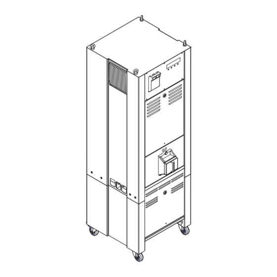
Description Lay-out of the equipment cabinets 3.4.1 Outside - small cabinet: 2.5 to 10 kVa Main items Thyristor heatsink Fused input switch User interface Lifting lugs (option) Series CutOut (SCO) (option) CS cabinet (option) Wheels (option) Ground stud M6 AM.07.360e - Edition 2.0... - Page 17 Description 3.4.2 Inside - small cabinet: 2.5 to 10 kVa Main items Input terminals (X1) Earth Fault Detection module (EFD) (option) Output measurement transformers (TI2, TI3) Tap (S6 to S1) Lightning arrestors (LA1, LA2) Output terminals (X2) Series choke (L1) Multiwire control (option) J-Bus logic (option) Thyristor Block Module (TBM)
- Page 18 Description 3.4.3 Outside - big cabinet 15 to 30 kVa Main items Thyristor heatsink Fused input switch User interface Lifting lugs (option) Series CutOut (SCO) (option) CS cabinet (option) Wheels (option) Ground stud M6 AM.07.360e - Edition 2.0...
- Page 19 Description 3.4.4 Inside - big cabinet 15 to 30 kVa Main items Input terminals (X1) Earth Fault Detection module (EFD) (option) Output measurement transformers (TI2, TI3) Lightning arrestors (LA1, LA2) Output terminals (X2) Tap (S6 to S1) Series choke (L1) Multiwire control (option) J-Bus logic (option) Thyristor Block Module (TBM)
- Page 20 Description 3.4.5 Overview of component connections C011 C012 C013 C014 C010 UI logic Fuse (F2) EFD (option) Output power transformer (T1) Main contactor (K1) Output measurement transformer (TI2, TI3) EFD resistors (option) LFD (option) Output terminals (X2) Series choke (L1) J-Bus interface (option) Fused input switch (F1) Multiwire logic (option)
-
Page 21: Components
Description Components 3.5.1 Power input Input terminals The input terminals connect the power input (X1) cables to the regulator. The size of these terminals depends on the input current rating of the regulator: Common mode The common mode choke blocks the high- choke frequency common-mode currents from the power circuitry. - Page 22 Description Fused input switch The fused input switch disconnects the (F1) equipment from the mains power supply. Fuses (F2, F3) The fuses F2 and F3 protect the wiring of the equipment from overcurrent: F2 protects the low current mains wiring; F3 protects the wiring to measure the primary voltage of the power transformer;...
- Page 23 Description Thyristors (THP1) The thyristors use phase control as a closed loop regulation system to obtain the required output current. 3.5.2 Power output Output power The transformer has a set of primary and transformer (T1) secondary taps. The primary taps can adapt to the typical input voltages of 220, 240, 380, 400 or 416 V - 50 or 60 Hz.
- Page 24 Description Output terminals The output terminals connect the equipment to (X2) the series circuit. Output terminals The output terminals connect the equipment to when you use a the series circuit. Lightning arrestors The output terminals connect the equipment to (LA1, LA2) the series circuit.
- Page 25 Description 3.5.3 Printed Circuit Boards (PCBs) Thyristor Block The TBM is the interface between the CCL and Module (TBM) the thyristor gates. The TBM PCB controls the thyristor gates to obtain the required conduction angle. The TBM also provides fast overcurrent protection and asymmetric output voltage monitoring.
-
Page 26: Working Principle
Description Local Master The LMC communicates with the other modules Controller (LMC) as a master via a local bus. The LMC processes and distributes the messages it receives from the other modules. Each slave has a control line to request transmission of data to the LMC. The local bus connection uses the RS485 protocol to send isolated signals over two wires. -
Page 27: Nameplate
Description Nameplate Each equipment has a standard nameplate: CONSTANT CURRENT REGULATOR REGULATEUR A COURANT CONSTANT SINGLE PHASE TYPE : BIPHASE 2P + T INPUT : 50/60Hz ENTREE : OUTPUT : SORTIE : REMOTE CONTROL : MAN. 8STEPS TELECOM : 8BRILL. MAX. OPTIONS : SERIES NR : NUMERO DE SERIE :... -
Page 28: Options
Description Options Remote control The equipment can be controlled remotely with Multiwire, J-Bus, or a combination of the above. The system automatically detects which communication method is available. Multiwire Each equipment has a maximum of three multiwire PCBs connected to the LMC: MW1;... - Page 29 Description Lamp Fault The LFD shows the number of defective light fittings on the UI. Detection (LFD) The operation of the LFD is based on the change in the output waveforms when a series transformer saturates as a consequence of the lamp having blown at the secondary side. The LFD can be used together with a CS.
-
Page 30: User Interface (Ui)
Description User interface (UI) You can operate the equipment with the UI. AM.07.360e - Edition 2.0... -
Page 31: Commissioning
Commissioning Commissioning Main commissioning procedure Do the first start-up. See § 4.2. Adjust the tap setting. See § 4.3. Calibrate the Lamp Fault Detection (LFD) module (option). See § 4.4. Calibrate the Earth Fault Detection EFD) module (option). See § 4.5. Adjust the number of available brightness steps. - Page 32 Commissioning 4.2.2 Measure output current in short-circuit Prepare Make sure that the tap setting is set to 8/8. See § 12.7. Make sure that all power to the equipment is OFF. See § 5.3. Open the front panel. See § 7.3. Remove the output cable.
- Page 33 Commissioning Short circuit with SCO (option) Set the SCO to mode C. See § 5.12. With the separate piece of output cable, short-circuit the output terminals. Connect AC True RMS multimeter Connect an AC True RMS multimeter (B) to the short-circuited cable (A) or the output power cable in the case of an SCO.
- Page 34 Commissioning Short circuit with SCO (option) Remove the SCO. See § 7.2.14. Measure the resistance of the series circuit: measure on the ends of the series circuit. Install the SCO. See § 7.2.14. Measure the insulation resistance: set the SCO to mode C (short circuit position). See §...
- Page 35 Commissioning Check brilliancy level Examine if all light fittings have the same brilliancy level. Go to the runway area to make a visual inspection. Check all brightness steps separately. Go through the whole procedure for each brightness step. Finish Wait for approximately 30 minutes and make sure that he equipment works correctly. Make sure that all power to the equipment is OFF.
- Page 36 Commissioning Short-circuit With the separate piece of output cable, short-circuit the series circuit terminals (A). Short circuit with SCO (option) Set the SCO to mode C. See § 5.12. Note The SCO makes sure that excessive output current does not damage the series circuit.
- Page 37 Commissioning Measure Select the step 6.6 A. See § 5.1. If the output current on the AC True RMS multimeter does not reach 6.6 A, change the series circuit configuration before you LOCAL MCR: NAME proceed. No Errors Vin : 400V LFD : 0 Lmp Iout:...
-
Page 38: Adjust Tap Setting
Commissioning Measure Push the Back button. The UI now shows the menu selection page. Push the Select button to go to the Setup menu. LOCAL MCR: NAME Push the STP up button until the Step field No Errors Vin : 400V LFD : 0 Lmp Iout:... - Page 39 Commissioning Switch equipment ON Set the equipment to LOCAL mode. See § 5.1. Select the step 6.6 A. If the output current does not reach 6.6 A, LOCAL MCR: NAME change the series circuit configuration No Errors Vin : 400V LFD : 0 Lmp Iout: 6.6A...
-
Page 40: Calibrate Lamp Fault Detection (Lfd) (Option)
Commissioning Adjust configuration Open the configuration software tool. Go to menu Installation. Click the field adjacent to the TAP-setting parameter. A window opens. Select the appropriate TAP setting. On the UI, push the Menu button once. Push the STP UP button until the lout field shows 6.6 A. - Page 41 Commissioning Enable the LFD function Select the menu LFD > Control commands. Set the parameter ON/OFF control to ‘Enabled’. Select LFD calibration Erase the calibration tables of all sets.. Select the menu LFD > LFD calibration. Select the set to calibrate.. If the equipment has a CS, define the combination of circuits that will be active for that set.
- Page 42 Commissioning Remove lamps Make sure that all power to the equipment is OFF. See § 5.3. Earth the series circuit with an earthing wire or with the SCO (See § 5.12). Remove a number of light fittings in the field. Note Choose the number of lamps in function of the alarm level you use.
-
Page 43: Calibrate Earth Fault Detection (Efd) (Option)
Commissioning Calibrate Earth Fault Detection (EFD) (option) If the equipment has an EFD, you must carry out this procedure. Note Use the configuration software tool. See chapter 10. Note The procedure below shows the configuration software tool. It is also possible to carry out the procedure on the UI. -
Page 44: Remote Control Configuration: Multiwire (Option)
Commissioning Calibrate Select Calibrate the EFD. Wait until the equipment finished the calibration procedure. Remote control configuration: multiwire (option) Note Use the configuration software tool. See chapter 10. Enable and test remote control Push the Remote button. You can see the status REMOTE on the UI. -
Page 45: Remote Control Configuration: J-Bus (Option)
Commissioning Remote control configuration: J-Bus (option) 4.7.1 General procedure Set the binary address of the LMC. Set the slave address. Choose and set a two or four wire communication type. Check the connection. 4.7.2 Set binary address of LMC PCB 1513 Set the dip-switches according to the databus connection of the equipment. - Page 46 Commissioning AM.07.360e - Edition 2.0...
-
Page 47: Operation
Operation Operation Note The manual shows who to change paramaters with the UI. You can also use the configuration software tool. See chapter 10. Switch ON in local mode When you switch ON the equipment, it starts to produce the same output current that was valid before the equipment was switched OFF. -
Page 48: Switch Off Power Supply
Operation Switch OFF power supply Small cabinet Switch OFF the fused input switch (A). Switch OFF the main power supply at the disconnection device. Open the main switch on the main distribution board. Disconnect the equipment from the series circuit. Big cabinet Switch OFF the fused input switch (A). -
Page 49: Adjust Number Of Used Brightness Steps
Operation Adjust number of used brightness steps 5.4.1 Used brightness steps All equipments are programmed with five steps by default. You can change the number of required steps. Table 5.1 shows the current values that the equipment produces at each step, depending on how many steps are programmed. -
Page 50: Switch Between Local And Remote Mode
Operation Switch between local and remote mode To control the equipment through the UI switch to the local mode. To control the equipment with the remote control system switch to the remote mode. Push the LOCAL or REMOTE button on the user interface. -
Page 51: View And Clear Errors
Operation View and clear errors The UI only displays information about errors that the equipment can detect. The equipment does not detect all possible errors. You have to observe if the equipment operates correctly. When a critical error occurs, the equipment stops automatically. The equipment does not store error messages and shows only the latest 15 error messages. -
Page 52: Activate With Cs (Option) In Local Mode
Operation Activate with CS (option) in Local mode If your system has a CS, you must activate separately all circuits that are in use. You can also deactivate circuits to stop the equipment from producing output current to them. On the start page, press Menu twice. Push the Down button until the asterisk (*) is next to MCR Control. -
Page 53: Examine Hour Counter Levels
Operation 5.11 Examine hour counter levels To check the amount of hours the equipment is ON or produces output current that is higher than a set value, check the hour counter levels. On the start page, press Menu twice. Press Start. Press Down until the asterisk is next to Hour Counters. -
Page 54: Use Series Cutout (Sco)
Operation 5.12 Use Series CutOut (SCO) WARNING Always wear protective gloves and shoes when working with the equipment or series circuit. 5.12.1 Operation mode The SCO has three operation modes: Description Mode A Mode B Mode C Purpose Normal operation. Maintenance operation. - Page 55 Operation 5.12.2 Adjust operation mode Remove cover Open the lock (A). Remove the cover (B). Use the handle. Set operation mode Install the cover (B). See the cover placement in § 5.12.1. Close the lock (A). AM.07.360e - Edition 2.0...
- Page 56 Operation AM.07.360e - Edition 2.0...
-
Page 57: Troubleshooting
Troubleshooting Troubleshooting WARNING Do not troubleshoot unless you have read and understood all the information in chapter 2 and you are qualified to work on high-voltage systems. Set the equipment to local control; Set the equipment to the brightness step OFF before you examine the series circuit. -
Page 58: Troubleshooting Guide
Troubleshooting Troubleshooting guide 6.2.1 Fault: Equipment does not turn ON Table: 6.1 Equipment does not turn ON Problem Possible cause Possible solution No local indications on Damaged fuse on fused switch. Replace the fuse. boards. See § 7.2.12. Damaged auxiliary power fuses Replace the fuse. - Page 59 Troubleshooting 6.2.2 Fault: Equipment turns ON but suddenly de-energizes Table: 6.2 Equipment turns ON but suddenly de-energizes Problem Possible cause Solution (See) Protection of the power Power supply, fuses or the Adjust the circuit breakers supply to the equipment protection is not correctly and/or the mains protection became operational.
- Page 60 Troubleshooting Problem Possible cause Solution (See) Alarm “Overcurrent error”. Overcurrent. Examine the maximum output current and adjust if necessary. Examine the overcurrent alarm level and adjust if necessary. See § 10.3.3. Defective circuit connections. Improve or restore the connections. Defective components. Replace the defective components.
- Page 61 Troubleshooting 6.2.3 Fault: equipment does not produce requested output current Table: 6.3 Equipment does not produce the requested output current Problem Possible cause Solution (See) Equipment produces the Maximum brightness step is Disconnect the remote maximum output current at always chosen. control line for the max.
- Page 62 Troubleshooting AM.07.360e - Edition 2.0...
-
Page 63: Maintenance
Maintenance Maintenance WARNING Only personnel authorized to work on high-voltage equipment can do maintenance work on the equipment. Operate the equipment under local control when you do maintenance work on the equipment to prevent the equipment from being accidentally switched ON. Obey all local safety procedures. -
Page 64: Part Replacement
Maintenance Part replacement WARNING Make sure you have read and understood all safety procedures and standards related to this equipment. See chapter 2. WARNING Make sure you switch OFF the power to the equipment. See § 5.3. CAUTION While you carry out maintenance, make sure that: You do not drop any screws or nuts inside the equipment cabinet. - Page 65 Maintenance 7.2.1 Required tools Measurement tools True RMS Multimeter; CAUTION The output voltage of the 30 kVA / 6.6 A equipment can reach approximately 4600 V at full load. An isolating measurement transformer for use on the 5000 V AC line is recommended.· Multimeter;...
- Page 66 Examine the firmware version Compare the firmware version on the identification of the new UI PCB with the version on the MCR Setup menu. See § 9.6. If the firmware version is not the same, contact ADB. 7.2.3 Local Master Controller (LMC) PCB Note Use the configuration software tool.
- Page 67 Compare the firmware version on the identification of the new LMC PCB with the version on the MCR Setup menu. See § 9.6. If the firmware version is not the same, contact ADB. Switch OFF the power supply. See § 5.3.
- Page 68 Maintenance 7.2.4 Current Control Logic (CCL) PCB Note Use the configuration software tool. See chapter 10. Prepare Examine if the firmware version on the identification of the new CCL PCB is correct. Switch ON the equipment. Use the fused input switch and the disconnection device. Open the configuration software tool.
- Page 69 Compare the firmware version on the identification of the new CCL PCB with the version on the MCR Setup menu. See § 9.6. If the firmware version is not the same, contact ADB. Switch OFF the power supply. See § 5.3.
- Page 70 Examine the firmware version Compare the firmware version on the identification of the new TBM PCB with the version on the MCR Setup menu. See § 9.6. If the firmware version is not the same, contact ADB. 7.2.6 Power Supply Logic (PSL) PCB Replace Switch OFF the power supply.
- Page 71 Maintenance 7.2.7 Multiwire MW1, MW2 or MW3 PCB (option) The procedure applies to both the 24 V DC and the 48 V DC multiwire PCB. Replace Switch OFF the power supply. See § 5.3. Record the position of dip switches SW5 and SW6.
- Page 72 Maintenance 7.2.8 J-Bus PCB (option) CAUTION When one equipment on the databus chain is disconnected, the other equipments on that databus are also disconnected at the same time. Replace Switch OFF the power supply. See § 5.3. Remove the rear panel. See § 7.3. Disconnect the cables and the earthing wire from the J-Bus PCB (B).
- Page 73 Examine the firmware version Compare the firmware version on the identification of the new EFD PCB with the version on the MCR Setup menu. See § 9.6. If the firmware version is not the same, contact ADB. AM.07.360e - Edition 2.0...
- Page 74 Maintenance EFD resistor The procedure applies to both the small and the big cabinet. In the small cabinets the EFD resistor is placed horizontally. In the big cabinets the EFD resistor is placed vertically. Replace Switch OFF the power supply. See § 5.3. Open the front panel.
- Page 75 Maintenance 7.2.10 Lamp Fault Detection (LFD) PCB (option) Note Use the configuration software tool. See chapter 10. Prepare Examine if the firmware version on the identification of the new LFD PCB is correct. Switch ON the equipment. Use the fused input switch and the disconnection device.
- Page 76 Examine the firmware version Compare the firmware version on the identification of the new EFD PCB with the version on the MCR Setup menu. See § 9.6. If the firmware version is not the same, contact ADB. 7.2.11 Circuit Selector (CS) PCB Replace Switch OFF the power supply.
- Page 77 Maintenance 7.2.12 Power components, input Fused input switch, Switch OFF the power supply. See § 5.3. small cabinet Turn the fuse holder (A) counter clockwise. Use the turning handle tool. Remove the fuse holder. Remove the fuse (B) from the fuse holder. Install the new fuse in the fuse holder.
- Page 78 Maintenance MOV1/A, MOV1/B Switch OFF the power supply. See § 5.3. (option) Open the front panel. See § 7.3. Replace the over-voltage protection plug-in module (A). Close the front panel. Main contactor (K1) Prepare Switch OFF the power supply. See § 5.3. Remove the top panel and the UI panel.
- Page 79 Maintenance Disconnect Loosen the screws of the cables (C) at the bottom of the main contactor. Disconnect the connectors A1 and A2 (B) on top of the main contactor (A). Disconnect the cables (C). Note When you disconnect the cables (C), also the connectors (D) become loose.
- Page 80 Maintenance Install - 2 Install the rail stopper (B). Tighten the screws of the rail stopper. Connect the cables 1 L1, 3 L2, 5 L3 and 7 L4 on top of the main contactor (A). Tighten the screws of the cables. Install the top panel and the UI panel.
- Page 81 Maintenance Remove - 2 Remove the crimp (A) that connects the mains filter cables and the cables 4 T2 and 6 T3. Install Install in the new mains filter. Install the crimp that connects the mains filter cables and the cables 4 T2 and 6 T3. Install the main contactor (A).
- Page 82 Maintenance Install Install the screws (A) and connect the new input measurement transformer (B) to the clamps (C). Install the cable (D) through the input measurement transformer. The cable is labeled A05. For an equipment with a current less than 63 A, make two loops through the input measurement transformer.
- Page 83 Maintenance Replace Remove the bolts (A). Remove the thyristor pack (B). Wipe clean the heat sink below the thyristor pack (C). Apply an even layer of conductive paste on the rear of the new thyristor pack. Install the new thyristor pack (B). Install the screws (A) and apply these torque values (Use a torque screwdriver.): Type CTT90GK (M5): Between 2.5...
- Page 84 Maintenance 7.2.13 Power components, output Lightning arrestors The procedure shows the replacement of three lightning arrestor modules as an example. The (LA1 - LA2), small procedure for all six lightning arrestors is identical. cabinet Prepare Switch OFF the power supply. See § 5.3. Open the front panel.
- Page 85 Maintenance Output current measurement transformer (TI2, TI3) Prepare Switch OFF the power supply. See § 5.3. Open the front panel. See § 7.3. Replace Disconnect the connectors (A). Use a pair of pliers if necessary. Disconnect the cable (B) at the output terminal 2.
- Page 86 Maintenance 7.2.14 Series CutOut (SCO) (option) Prepare Switch OFF the power supply. See § 5.3. Make sure that the circuit is earthed. Remove the cover of the SCO (A). Remove Loosen the screws (A1). Remove the series circuit cables from the earthing bar (A2).
- Page 87 Maintenance Install Install the new SCO. Install the bolts (D). Connect the earthing wire (C). Use the screw connection (C1). Connect the output cables (B). Tighten the screws B1. Connect the series circuit cables (A). Tighten the screws (A1). Connect the wires to the earthing bar (A2). Make the connection of the shield of the cable to the earthing bar.
- Page 88 Maintenance Remove - 2 Remove the high-voltage contactor (A). Push down (I) and pull (II) the high-voltage contactor. Install Install the new high-voltage contactor. Push the HV-contactor on the rail (C). Install the rail stopper (B). Connect the cables (A). Tighten the screws of the cables.
- Page 89 Maintenance CSM voltage transformer (CS - K1 - K8) Prepare Switch OFF the power supply. See § 5.3. Remove the rear panel of the CS cabinet. See § 7.3. Pull out the cables from the input supply terminals (A). Replace Remove the bolt (A).
-
Page 90: Remove Panels
Maintenance Remove panels The panels of the equipment can be removed for installation or maintenance procedures. CAUTION Do not operate the equipment with any of the panels removed. Do not mix panels from different equipments. Always connect the earthing wires before you install the panels. 7.3.1 Front and rear panel Remove panel... - Page 91 Maintenance 7.3.2 Top panel Remove the bolts (A) or the optional lifting lugs (B). Remove the panel (C). 7.3.3 UI panel: small cabinet Remove panel Remove the screws (A). Remove the panel (B). Disconnect wires Disconnect the power cable from connector J1 (A).
- Page 92 Maintenance 7.3.4 UI panel: big cabinet Remove fused input switch and complete handle (A) Open the handle (I). Move up the handle (II). Pull and remove the handle (III). Remove panel Loosen the screws (A). Remove the panel (B). Disconnect wires Disconnect the power cable from connector J1 (A).
-
Page 93: Checks And Measurements
Checks and measurements Checks and measurements Measure input voltage Make sure that the main switch is OFF. Make sure that the input supply cables that come from the mains distribution panel are anly connecte to the equipment you want to measure. Switch on the mains distribution to feed the equipment you want to measure. -
Page 94: Calculate Resistance Of Series Circuit
Checks and measurements Calculate resistance of series circuit = ρ x L/A + y x 0.1212 prim Where: = resistance of the series circuit in Ohm prim ρ = 18 x 10 (Ohm x mm L = length of the circuit in m A = section of the cable in mm y = number of series transformers in the circuit Example:... -
Page 95: User Interface (Ui)
User Interface (UI) User Interface (UI) User Interface (UI) Overview Push-buttons Menu rows Push-button functions Title row Navigate the User Interface (UI) Use the push-buttons to navigate through the menus. The UI shows the selected function of each push-button above the push-button. The table shows the available functions for the push-buttons: Table: 9.1 Push-button functions... -
Page 96: Control Modes
User Interface (UI) Control modes The UI shows the selected control mode on the title row. See table 9.2 below. Table: 9.2 Control modes Mode Description LOCAL To control the equipment with the UI. All the parameters are accessible to read and to modify. REMOTE To control the equipment with a remote control system. -
Page 97: Mcr Setup Menu
User Interface (UI) MCR Setup menu 9.6.1 Output current To change the settings for the output current. Table: 9.5 MCR output current menu Item Range Nominal output current [A] 6.6 or 8.3 or 12 or 20 Overcurrent level 1 [%] 2.0 - 7.5 Overcurrent delay 1 [s] 1.0 - 12.0... - Page 98 Default CSM To set each circuit to ON / OFF. 9.6.4 Supply voltage CAUTION First contact ADB if you want to change any of these parameters. Wrongly set parameters can damage the equipment. Table: 9.8 Supply voltage menu Item Range...
-
Page 99: Circuit Selector Module (Csm) Or Aglas Menu (Options)
User Interface (UI) 9.6.5 Table: 9.9 IO menu Item Range Multiwire 1 The system detects the available multiwire modules. Multiwire 3 is reserved for the CS. You cannot change the input / output Multiwire 2 functions wit the UI. To change these functions, use the Multiwire 3 configuration software tool, see §... -
Page 100: Earth Fault Detection (Efd) Menu (Option)
User Interface (UI) Earth Fault Detection (EFD) menu (option) Table: 9.11 Earth Fault Detection menu Item Range EFD Control Disabled / enabled EFD Reset error YES / NO EFD ON if MCR is OFF YES / NO If the parameter is set to YES, the EFD works even if the equipment is switched OFF. -
Page 101: Lamp Fault Detection (Lfd) Calibration Menu (Option)
User Interface (UI) 9.10 Lamp Fault Detection (LFD) calibration menu (option) Table: 9.12 LFD Calibration menu Item Description LFD View sets To display the different circuit combinations (sets) for the LFD calibration. There are 1, 2, 4, or 8 sets available, depending on the installed options. -
Page 102: Display Menu
User Interface (UI) 9.12 Display menu Table: 9.14 Display menu Item Description Display Contrast [%] Locked to 100 %. Display time-out [s] Range: 5.0 to 124.5 seconds. 124.5 seconds locks the display, that is, the back light always remains ON and the display shows LOCK. Embedded language To shows the main language of the UI. - Page 103 User Interface (UI) Alarm text / message Alarm Description status: error (E) / warning (W) OVERTEMPERATURE The equipment is too hot. Mains supply is LOW The mains supply voltage drops below a preset level, the equipment switches OFF. The equipment switches OFF; When the mains supply voltage has reached a higher (user- adjustable) level again, the...
- Page 104 User Interface (UI) Table: 9.17 Lamp Fault Detection (LFD) faults Alarm text (message) Alarm Description status: error (E) / warning (W) LFD warning level reached The LFD unit has reached the set number of burnt lamps for level 1. LFD alarm level reached The LFD unit has reached the set number of burnt lamps for level 2.
-
Page 105: Configuration Software Tool
Configuration software tool Configuration software tool With the configuration software tool, you can operate the equipment from a PC. WARNING When you activate the configuration tool, you transfer all control of the equipment to the configuration software tool. In this situation, remote or local control of the equipment is not possible. - Page 106 Configuration software tool Start software Switch the equipment ON. The equipment also supplies power to the dongle. Click the MCR_WIN.exe file in the directory where you installed the software. The configuration tool opens. Select the menu Configuration. Select the applicable serial communication port (COM) to which you connected the dongle. Note The baud rate and parity settings for the communication between the PC, dongle and the equipment must be the same.
-
Page 107: Description Of Screens And Menus
Configuration software tool 10.3 Description of screens and menus 10.3.1 Configuration software tool screen Menu bar Active menu view Status view Error message Communication connection status view Table: 10.1 Screen structure Screen item Description Menu bar The screen item shows the available menu items and the Exit button. - Page 108 Configuration software tool 10.3.2 Control menu Table: 10.2 Control menu Item Range Step To change the selected brightness step. Circuit 1 - 8 To set the enabled circuits ON or OFF if the equipment has a Remote reset To reset the equipment. 10.3.3 MCR Setup menu Identification and...
- Page 109 Configuration software tool Mains supply Table: 10.4 Mains supply menu Item Range Mains supply & frequency Shows information about the mains supply. You can change these values in the Installation menu. Alarm levels To define alarm levels for the mains supply. CS (option) Table: 10.5 CS menu (option)
- Page 110 Configuration software tool Input/output measurements Table: 10.7 Input/output measurements menu Item Range Measurements Shows the different input and output values. Calibration To calibrate input and output measurements for the CCL module. WARNING Any calibration is potentially harmful because high voltages and currents are involved.
- Page 111 Configuration software tool 10.3.4 Earth Fault Detection (EFD) menu (option) Table: 10.9 EFD menu Item Range Control commands To enable or disable the EFD module. EFD Calibration To start the calibration. After a successful calibration, the module can correctly measure the leakage current of the field circuit.
- Page 112 To upload a previously saved IO settings profile to the unit. 10.3.8 Installation menu CAUTION First contact ADB if you want to change any of these parameters. Wrongly set parameters can damage the equipment. Table: 10.13 Installation menu Item Range...
-
Page 113: Pcb Drawings And Settings
PCB drawings and settings PCB drawings and settings 11.1 LED RUN Each PCB has LED lights that have specific functions related to that PCB. The general function is given in the table below. Table: 11.1 General LED RUN light functions LED RUN Description Blinks once per second... -
Page 114: Ui - Pcb1507
PCB drawings and settings 11.2 UI - PCB1507 11.2.1 Printed Circuit Board (PCB) AM.07.360e - Edition 2.0... - Page 115 PCB drawings and settings 11.2.2 Connectors Table: 11.2 UI connectors Connector Connection to Power supply Local bus 11.2.3 Dip-switches Factory setting of the dip-switch banks: 2 3 4 5 6 7 8 SW2: 2 3 4 5 6 7 8 SW1: Local Bus - Line termination Table: 11.3...
- Page 116 PCB drawings and settings SW2: Various functions Table: 11.4 Dip-switch bank SW2: various functions Dip-switch Function Not used Not used ON: Lock in boot-loading mode Not used Local Bus - 9600 19200 38400 9600 baudrate: Local Bus - EVEN parity: parit parity parity...
-
Page 117: Multiwire - Pcb1486 (Option)
PCB drawings and settings 11.3 Multiwire - PCB1486 (option) Note It is impossible to attribute the same function to more than one terminal. 11.3.1 Layout of the Printed Circuit Board (PCB) GNDext Vext(48 V DC) Vext(48 V DC) GNDext Common Common Output 8 Input 8... - Page 118 PCB drawings and settings 11.3.2 Straps Table: 11.6 Multiwire PCB straps Strap Description Internal voltage for remote control. Internal voltage for back indication signals. 11.3.3 Connectors Table: 11.7 Multiwire PCB connectors Connector Connection to Back-indication/output signals The connector type is WAGO 231-312/026-000 cage-clamp connector. This connector can accept wires of 0.08 to 2.5 mm (28 - 12 AWG).
- Page 119 PCB drawings and settings Table: 11.9 Factory settings for the MW control signals MW1 output MW2 output MW3output Step 1 obtained Over current alarm 1 Circuit 1 active Step 2 obtained Open circuit alarm Circuit 2 active Step 3 obtained EFD warning level Free Step 4 obtained...
- Page 120 PCB drawings and settings Function Description Step 1 Selection for brightness steps. Step 2 Step 3 Step 4 Step 5 Step 6 Step 7 Step 8 Reset EFD Reset EFD alarms, levels 1 and 2. error Use LFD Cancel the back-indication of LFD alarm, level 1. degraded mode Allow WRITE...
- Page 121 PCB drawings and settings 11.3.6 Output terminals With external power supply With internal power supply (polarized With internal power supply (polarized contacts negative) contacts positive) The table shows an example of functions you can configure to the output connector P1 of PCBs MW1 or MW2.
- Page 122 PCB drawings and settings Function Description LFD warning Level 1, preset quantity of burnt lamps, is reached. The warning disappears level after the condition is no longer detected. LFD alarm level Level 2, preset quantity of burnt lamps, is reached. The warning disappears after the condition is no longer detected.
-
Page 123: J-Bus - Pcb1502 (Option)
PCB drawings and settings Table: 11.15 Connect P1 wires, depending on the power supply Back External power supply Internal power supply Internal power supply indication (polarized contacts (polarized contacts positive) (B) negative) (C) Remarks Remove strap W6, Remove strap W6 Install strap W6 Max. - Page 124 PCB drawings and settings 11.4.1 Layout of the Printed Circuit Board (PCB) The PCB provides the interconnection of the user J-Bus(ses) with the LMC. The PCB has gas arrestors for overvoltage protection. Description: P1: Bus A connection to the substation on the master; P3: Bus B connection to the substation on the master;...
- Page 125 PCB drawings and settings 11.4.2 Connectors Table: 11.16 J-Bus connectors Connector Connection to J-Bus control for Bus A J-Bus control for Bus A J-Bus control for Bus B J-Bus control for Bus B Table: 11.17 Wiring for connectors P1-P4 Wire Description Tx + Rx +...
- Page 126 PCB drawings and settings Two-wire dual databus for Bus A and Bus B (RS-485 protocol standard): Two-wire single databus for Bus A (RS-485 protocol standard): AM.07.360e - Edition 2.0...
-
Page 127: Local Master Controller (Lmc) - Pcb1513
PCB drawings and settings 11.5 Local Master Controller (LMC) - PCB1513 11.5.1 Printed Circuit Board (PCB) C011 C012 C013 C014 C010 AM.07.360e - Edition 2.0... - Page 128 PCB drawings and settings 11.5.2 Connectors Table: 11.18 LMC connectors Connector Type Connection to 20-pin, flat connector, grey 10-pin, flat connector, blue Local bus 20-pin, flat connector, blue EFD PCB 9-pole, Sub-D female Dongle 6-pin Phoenix, grey Power supply 26-pin, flat connector, grey 26-pin, flat connector, grey 26-pin, flat connector, grey 3-pin stocko...
- Page 129 PCB drawings and settings Table: 11.19 Dip-switch bank SW1 J-Bus A line termination Dip-switch Function ON: Transmit / E – pull up 680 Ohm ON: Transmit / E – line termination 150 Ohm ON: Transmit / E – pull down 680 Ohm OFF = 2 wire / ON = 4 wire ON: Receive / R –...
- Page 130 PCB drawings and settings Table: 11.22 Dip-switch bank SW5 local bus modules Dip-switch Function ON: UI enabled ON: EFD enabled ON: LFD enabled Not used Not used Not used Not used ON: dongle enabled SW6 Various functions Table: 11.23 Dip-switch bank SW6 various functions Dip-switch Function ON: Local Kill...
- Page 131 PCB drawings and settings 11.5.5 Two/four wire communication Table: 11.25 Two-wire communication Dip-switch Function ON: Transmit / E – pull up 680 Ohm ON: Line termination 150 Ohm. Set this ON only for the last equipment on the databus. ON: Transmit / E – pull down 680 Ohm OFF = 2 wire Table: 11.26 Four-wire communication Dip-switch...
-
Page 132: Thyristor Block Module (Tbm) - Pcb1517
PCB drawings and settings 11.6 Thyristor Block Module (TBM) - PCB1517 11.6.1 Printed Circuit Board (PCB) 11.6.2 Connectors Table: 11.27 TBM connectors Connector Type Connection to 10-pin, flat connector, grey Local bus 6-pin WAGO, orange Not in use 6-pin Phoenix contact, green CCL PCB 20-pin, flat connector, grey Thyristor bank... - Page 133 PCB drawings and settings 11.6.3 Dip-switches Factory setting of the dip- switches:S1 - all ONS2 - 1:OFF 2:OFF 3:OFF 4:ON 5:OFF 6:ON 7:ON 8:ON SW1: 2 3 4 5 6 7 8 SW2: 2 3 4 5 6 7 8 S1 Local Bus - Line termination Table: 11.28 Dip-switch bank S1 local bus line termination...
- Page 134 PCB drawings and settings S2 Various functions Table: 11.29 Dip-switch bank S2 various functions Dip- switch Function Recall default parameters CCL-TBM communication, parity: For 115200 Bd: 0 = even / 1 = odd For 38400 Bd: 0 = even / 1 = no parity ON: Lock in boot-loading mode CCL-TBM communication, baudrate: 0 = 115200 Bd / 1 = 38400 Bd Local Bus -...
-
Page 135: Power Supply Logic (Psl) - Pcb1521
PCB drawings and settings 11.7 Power Supply Logic (PSL) - PCB1521 11.7.1 Printed Circuit Board (PCB) CAUTION To prevent any damage or electrical shock on the Capacitor, discharge the Capacitor with the power resistor. The capacitor remains charged at about 70 V DC a long time after the equipment is disconnected from the power supply. - Page 136 PCB drawings and settings 11.7.2 Connectors Table: 11.31 PSL connectors Connector Connection to Power input supply SCO to X2 (option). If the equipment does not have a SCO, make the connector jumpered. Power output to the MW boards Current transformer Overvoltage protection (MOV1) Back-indication signals ON and REG.ERR (optional) DC power distribution...
-
Page 137: Current Control Logic (Ccl) - Pcb1516
PCB drawings and settings 11.8 Current Control Logic (CCL) - PCB1516 11.8.1 Printed Circuit Board (PCB) 11.8.2 Connectors Table: 11.33 CCL connectors Connector Type Connection to 20-pin, flat connector, grey TBM PCB 10-pin, flat connector, blue Local bus 3-pin WAGO, grey LFD PCB 26-pin, flat connector, grey CS PCB... - Page 138 PCB drawings and settings 11.8.3 Dip-switches Factory setting of the switches: SW1: 2 3 4 5 6 7 8 SW2 (00010111) 2 3 4 5 6 7 8 SW1 Local Bus - Line termination Table: 11.34 Dip-switch bank SW1 local bus line termination Dip-switch Function ON: Transmit / E –...
-
Page 139: Lamp Fault Detection (Lfd) - Pcb1519 (Option)
PCB drawings and settings 11.8.4 LEDs Table: 11.36 CCL LED RUN light functions Function Micro controller – RUN Local Bus – isolated 5 V present Local Bus – TXD Local Bus – TXD 11.9 Lamp Fault Detection (LFD) - PCB1519 (option) 11.9.1 Printed Circuit Board (PCB) 11.9.2... - Page 140 PCB drawings and settings 11.9.3 Dip-switches Factory setting of the switches: SW1: (all OFF) 2 3 4 5 6 7 8 SW2: 2 3 4 5 6 7 8 SW1 Local Bus - Line termination Table: 11.38 Dip-switch bank SW1 local bus line termination Dip-switch Function ON: Transmit / E –...
- Page 141 PCB drawings and settings 11.9.4 LEDs Table: 11.40 LFD LED RUN light functions Function Micro controller – RUN Local Bus – isolated 5 V present Local Bus –TXD Local Bus – RXD AM.07.360e - Edition 2.0...
-
Page 142: Earth Fault Detection (Efd) - Pcb1514 (Option)
PCB drawings and settings 11.10 Earth Fault Detection (EFD) - PCB1514 (option) WARNING Be careful when you handle the EFD PCB. The EFD produces a voltage of 500 V DC. This voltage is connected to the output circuit of the equipment, thus all high-voltage components have this voltage level relative to ground. - Page 143 PCB drawings and settings 11.10.2 Connectors Table: 11.41 EFD connectors Connector Connection to Power supply High-voltage connection from the resistor to C02 Local bus 11.10.3 Dip-switches Factory setting of the dip-switches: SW1 (all OFF): 2 3 4 5 6 7 8 SW2: 2 3 4 5 6 7 8 SW1 Local Bus -...
-
Page 144: Earth Fault Detection (Efd)-Resistor - Pcb1515 (Option)
PCB drawings and settings SW2 Various functions Table: 11.43 Dip-switch bank SW2 various functions Dip-switch Function Not used Not used ON: Lock in boot-loading mode Not used Local Bus - 9600 19200 38400 9600 baudrate: Local Bus - EVEN parity: parity parity parity... -
Page 145: Circuit Selector - Pcb1523 (Option)
PCB drawings and settings 11.11.2 Connectors Table: 11.45 EFD-Res connectors Connector Connection to Output terminal 11.12 Circuit Selector – PCB1523 (option) 11.12.1 Printed Circuit Board (PCB) 11.12.2 Connectors Table: 11.46 CS connectors Connector Connection to Control and power Feedback connection from the contactors AM.07.360e - Edition 2.0... - Page 146 PCB drawings and settings 11.12.3 Test points Table: 11.47 CS test points Test point Function Ground, relative to +12 V DC signal +12 V DC signal for relay control – K1 to K4 +12 V DC signal for relay control – K5 to K8 11.12.4 LEDs Table: 11.48 CS LED RUN light functions...
-
Page 147: Technical Data
25 and 30 kVA, only for 380/ 400/ 415 V. Some readjustments are possible in the ranges 220 - 240 V and 380 - 415 (420 V). For readjustments, contact ADB. The net weights depend on the chosen configuration. AM.07.360e - Edition 2.0... -
Page 148: Applicable Standards
Technical data 12.2 Applicable standards The equipment is in accordance with these standards: Table: 12.2 Applicable standards Standard Description ICAO Aerodrome Design Manual, Part 5 paragraphs 3.2.1.4/5/6 AC 150/5345-10F and L829 IEC 61822 12.3 ElectroMagnetic Compatibility (EMC) The equipment is designed to operate in an industrial electro-magnetic environment. The regulator complies with IEC 61822, in accordance with IEC 61000-6-4 and IEC 6-6-2 (generic standard for industrial environment). -
Page 149: Dimensions
Technical data 12.5 Dimensions The small cabinet (A) and the big cabinet (B): Table: 12.3 Dimensions Item A - 2.5 to 10 kVa B - 15 to 30 kVA X [mm] Y [mm] Z1 [mm] Z2 [mm] 1280 Dimensions with options [mm] Wheels Height + 100 Lifting lugs... -
Page 150: Taps
Technical data 12.7 Taps 12.7.1 Tap setting connections The figure shows the wire connections for different taps. AM.07.360e - Edition 2.0... - Page 151 Technical data Overview of the taps: Example: correct tap 6/8 setting for: 7.5 kVA equipment; Supply voltage: 380 V; Measured voltage reading on the terminals of fuse holder F3: 210 V. 12.7.2 Tap selection tables Table: 12.5 Tap settings for 2.5 kVA equipment 2.5 kVA Supply voltage [V] Tap setting...
- Page 152 Technical data Table: 12.7 Tap settings for 5 kVA equipment 5 kVA Supply voltage [V] Tap setting Measured 199-176 208-184 217-192 343-302 360-318 378-334 voltage [V] 174-151 182-158 191-164 301-259 317-273 333-287 150-101 157-105 163-110 258-173 272-182 286-191 100-51 104-53 109-55 172-87 181-91...
- Page 153 Technical data Table: 12.11 Tap settings for 20 kVA equipment 20 kVA Supply voltage [V] Tap setting Measured 211-185 221-195 223-204 368-323 384-337 405-355 voltage [V] 184-156 194-167 203-175 322-277 336-289 354-305 158-106 166-112 174-117 276-185 288-193 304-204 105-54 111-56 116-59 184-93 192-97...
-
Page 154: Parts List
Always mention serial number and type of the equipment. These are indicated on the nameplate of the equipment. For all spare part orders, contact ADB or our local representative. Recommendations To reduce downtime during maintenance, have one or more extra equipment cabinets in stand- by at the substation. - Page 155 Technical data 12.8.2 Standard Printed Circuit Boards (PCBs) Table: 12.15 Standard PCBs Item Description Part number Quantity per order PCB1507 - User Interface 1593.14.000 PCB1513 - Local Master Circuit 1593.14.113 PCB1516 - Current Control Logic 1590.03.541 PCB1517 - Thyristor Block Module 1593.14.213 PCB1521 - Power Supply Logic 1593.14.402...
- Page 156 Technical data 12.8.4 Firmware versions of PCBs Table: 12.17 Official firmware version of PCBs Item Latest firmware version Dongle 2.00 2.01 2.01 2.00 2.00 Note The firmware versions show the latest version available at the time of writing of this manual.
- Page 157 Technical data Item Description Part number Quantity per order Fused switch Fuse M1.6 A HBC DIA 6.3 L 32 6130.27.005 F2, F3 (medium) Fused switch Fuse T4 A HBC DIA 6.3 L 32 (slow- 6130.37.180 F4 (option) blow) PSL / F1 Fuse T1A HBC DIA 5 L20 (slow-blow) 6130.26.134 PSL / F2...
- Page 158 Technical data Table: 12.20 Internal and external fuses for 380 to 416 V (400 V IEC) equipments Input supply voltage 380 to 416 V (400 V IEC) Output Fuse in fused switch External fuse [A] power [kVA] Rating [A] Type Neozed Neozed Neozed...
- Page 159 Technical data Input supply voltage 380 to 416 V (400 V IEC) Output Current rating Thyristor Main contactor power (kVA) CTT90GK12 3RT1326+3RT1926-1CD00 CTT90GK12 3RT1326+3RT1926-1CD00 CTT165GK12 3RT1336+3RT1936-1CD00 CTT165GK12 3RT1336+3RT1936-1CD00 CTT165GK12 3RT1344+3RT1936-1CD00 12.8.6 Power components, output Table: 12.23 Power output components Item Description Part number Quantity...
- Page 160 Technical data 12.8.8 Power components, choke Table: 12.25 Power choke components Item Description Part number Quantity per order Series choke, 2.5 kVA 1476.02.500 Series choke, 4 kVA 1476.02.504 Series choke, 5 kVA 1476.02.505 Series choke, 7.5 kVA 1476.02.507 Series choke, 10 kVA 1476.02.510 Series choke, 15 kVA 1476.02.515...
- Page 161 Technical data 12.8.10 Hardware Table: 12.27 Hardware components Item Description Part number Quantity per order Wheels (optional) Fixed Wheel 7015.35.241 Wheels (optional) Wheel with lock 7015.35.251 Lifting lugs (optional) Lifting lugs M12 7015.20.120 Standoffs for PCBs M3 L10 7510.08.300 Nut Hex M3 for PCB mounting 7154.04.010 Wiring Cable clamp, for cable diameter up to 8...
- Page 162 Tel: +86 10 8476 0106 P.O. Box 341218 Fax: +86 10 8476 0090 United Arab Emirates Tel: +971 4372 4970 ADB Airfield Solutions GmbH & Co. KG Fax: +971 4372 4975 Von-der-Tannstr. 31 90439 Nürnberg Germany Unit 44 Business Innovation Centre...
Need help?
Do you have a question about the MCR3 2.5 to 10 kVa and is the answer not in the manual?
Questions and answers