Table of Contents
Advertisement
Quick Links
The Leader in Airfield Lighting
INSTRUCTION MANUAL
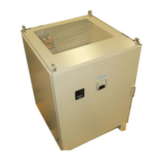
L-828 Constant Current Regulators
Additional manuals are available upon request for a nominal charge of $25.
30 KW/6.6A
LC-TYPE
Manufactured per FAA Specification
AC 150/5345-10E
ADB
A SIEMENS COMPANY
977 Gahanna Parkway
Columbus, Ohio 43230
Tel: (614) 861-1304
Fax: (614) 864-2069
Copyright © 1993 by ADB, Inc. All rights reserved.
Document No. 96A0147
Issued: 6/1/92
Rev. Date
Advertisement
Table of Contents
Troubleshooting

Related Manuals for ADB L-828


Summary of Contents for ADB L-828
- Page 1 Manufactured per FAA Specification AC 150/5345-10E A SIEMENS COMPANY 977 Gahanna Parkway Columbus, Ohio 43230 Tel: (614) 861-1304 Fax: (614) 864-2069 Additional manuals are available upon request for a nominal charge of $25. Copyright © 1993 by ADB, Inc. All rights reserved.
- Page 2 RECORD OF CHANGES Page Rev. Description Chkd App'd Document No. 96A0147 Page ii...
-
Page 3: Table Of Contents
TABLE OF CONTENTS Page 1. GENERAL INFORMATION AND REQUIREMENTS ................. 1-1 1.1 INTRODUCTION ............................... 1-1 1.2 S ................................... 1-1 COPE 1.3 P ................................1-1 URPOSE 1.4 EQUIPMENT DATA ............................1-2 1.5 PROTECTIVE DEVICES ........................... 1-2 1.6 REGULATION ..............................1-2 1.7 INDICATORS ..............................1-2 1.8 INPUT VOLTAGE .............................. - Page 4 ................1-6 ABLE UTPUT URRENT EVELS AND OLERANCES 1-6. R ..................1-6 ABLE ECOMMENDED NPUT OWER UPPLY 1-7. I L-828 C ............1-6 ABLE NPUT URRENT FOR ONSTANT URRENT EGULATORS 3-1. R S1 P 3- & 5-S ................3-1 ABLE OTARY...
- Page 5 (1) year from date of installation or a maximum of two (2) years from date of shipment will be corrected by repair or replacement by ADB, Inc., f.o.b. factory. Damage resulting from improper installation does not constitute proper and normal use and is not covered by the warranty.
-
Page 6: General Information And Requirements
GENERAL INFORMATION AND REQUIREMENTS 1.1 INTRODUCTION The ADB, Inc. 30 kW L-828 “LC-Type” Constant Current Regulators are designed to supply either three or five precision output current levels (6.6 amp maximum) for series lighting circuits on airport runways and taxiways. The regulators are air cooled and designed to accurately regulate the output current to within ±3% of the adjustable nominal level from no load to full load and with input voltage variations of... -
Page 7: Equipment Data
1.4 EQUIPMENT DATA Table 1-1 gives the part numbers for the 30 kW “LC-Type” regulators manufactured by ADB, Inc. Reference data pertinent to the equipment is listed in Table 1-2. Table 1-3 lists equipment and accessories supplied. Information on items not supplied but which might be required for installation is given in Table 1-4. -
Page 8: Input Voltage
1.8 INPUT VOLTAGE The standard power transformer for the L-828 regulators is designed for an input voltage of either 208/220/240 V ac (using field-adjustable tap, see Section 7.6) or 480 V ac. See the nameplate on the regulator for the input voltage rating. -
Page 9: Table 1-2. Equipment Data
The load before opening the isolation transformer secondaries may be any value from half to full load. Optional Input Lightning Protection: ADB #94B0011-1 for 480 V ac input; #94B0011-2 for 208- 240 V ac input. Terminal Blocks: Pressure-type for external remote control wiring Document No. -
Page 10: Table 1-3. Equipment Nots
• The LC-type CCR is not currently designed to be used with an ADB Mark II or III (PC board) lamp-out monitor. Monitoring is accomplished using the ADB “Scanning Monitor”. See Catalog Sheet #1228. -
Page 11: Table 1-4. Equipment Supplied
See the CCR’s nameplate for the kW rating and input voltage to determine the input current from Table 1-7. If no standard size circuit breaker exists at the 125% value, use the next larger standard size circuit breaker. Table 1-7. Input Current for L-828 Constant Current Regulators 208 V 220 V... -
Page 12: Theory Of Operation
THEORY OF OPERATION 2.1 Introduction Current regulation is obtained by using SCRs to switch the supply power (varying the “on” duration of the AC cycle) to the power transformer and by using feedback circuitry to monitor the transformer’s output. The brightness level is selected from one of three or five preset values. When the load varies, the feedback circuit changes the control-voltage level, which changes the conduction angle of the AC voltage to the SCRs to allow power to flow into the power transformer. -
Page 13: Transformers
2.4 Transformers Transformer T6 provides 120 V ac remote-control source voltage at TB2 terminal 8 through fuse F5. Transformers T3 and T4 provide AC voltage to the Control PCB. T3 provides 120/60 V ac. T4 provides 36/18 V ac. Document No. 96A0147 Page 2-2... -
Page 14: Operation
3. OPERATION 3.1 Control The rotary switch S1 on the front panel is used for local control of the regulator. This control switch has seven positions for 5-step CCR labeled: REM (remote), OFF, and brightness steps 1, 2, 3, 4 and 5 (or five positions for 3-step CCR: REM, OFF, 10, 30, 100). -
Page 15: Shutdown Procedure
2. When there are no remote control connections on terminal block TB2, the position REM becomes an additional OFF position, i.e., the regulator is deenergized when switch S1 is set to REM. 3. If more than one remote intensity is accidentally selected, the highest intensity will be selected. -
Page 16: Preventive Maintenance
PREVENTIVE MAINTENANCE 4.1 GENERAL This section establishes the maintenance procedures required for the constant current regulators. The maintenance tasks must be performed on a recurring basis to insure optimum performance, minimize service interruptions and avoid major breakdowns. WARNING Only personnel authorized to work on high-voltage equipment should perform maintenance on the regulator. -
Page 17: Open-Circuit Test
3-Step CCR S1 Position Allowable Range (Panel Ammeter) Amperes 4.55-4.94 5.33-5.67 6.40-6.70 5-Step CCR S1 Position Allowable Range (Panel Ammeter) Amperes 2.72-2.88 3.30-3.50 3.98-4.22 5.04-5.36 6.40-6.70 4. If the output current is not within the above specified limits, check the input voltage to regulator. The supply voltage should be within -5% to +10% of the nominal input voltage shown on the regulator nameplate. -
Page 18: Table 4-1. Preventivem
Table 4-1. Preventive Maintenance Tasks INTERVAL MAINTENANCE TASK ACTION Daily (1) Check all control equipment (1) Check local and remote control (if used) on each for proper operation brightness step. Monthly (1) Check input voltage (1) If input voltage is not within -5% to +10% of the nominal value specified on the nameplate of the regulator, notify power company to correct voltage. -
Page 19: Troubleshooting
5. TROUBLESHOOTING 5.1 Troubleshooting Table Preliminary troubleshooting information is given in Section 5.2. The troubleshooting guide for the LC- type L-828 constant current regulator is given in Table 5-2. WARNING Only personnel authorized to work on high-voltage equipment should perform troubleshooting on the regulator. -
Page 20: Table 5-1. Fuses
Table 5-1. Fuses Circuit Breaker CB1 Protects K1 (contacts), SCR1, L1, L2, (on 208-240 V LC) and main transformer T1 Fuse F1, F2 90A, Slo-Blo for 480 V CCRs Protects main transformerT1, contactor (on 480 V LC) 200A, Slo-Blo for 208, 220, & 240 K1 (contacts),SCR1, L1, and L2 CCRs Fuse F3, F4... -
Page 21: Table 5-2. Troubleshooting
Table 5-2. Troubleshooting Guide Problem: Regulator does not turn on using control switch S1. Test Repair (1) Turn off CCR using local control Circuit breaker CB1 is tripped. Reset CB1 by switching switch S1. Then turn CCR on. Verify CB1 on. If CB1 trips again check and replace fuses F1 that nothing happens and that green and F1. - Page 22 Table 5-1. Troubleshooting Guide Problem: Regulator repeatedly causes fuses F1/F2 to blow (orCB1 to trip) on start up. Test Repair (1) Turn control switch S1 to OFF. Replace feedback transformer T2/main transformer T1. Replace blown fuses F1/F2 (or reset CB1). While observing the CCR’s output ammeter, turn CCR on.
- Page 23 Test Repair (1) Test load for open-circuit Repair lighting loop. condition. Also, short CCR’s output TB1 and check for normal operation. See calibration instructions in Section 7.5. (2) Inspect contacts of contactor K1. Replace contactor K1 if defective. (3) Inspect transformer T5 and R5 Replace T5 or R5.
- Page 24 Figure 8-6. made for 208-240 V ac CCR input, or vice-versa, contact ADB Sales Department. WARNING: A CCR wired for 480 V ac must not be changed to 240, 220 or 208 V ac. A CCR wired for 240, 220 or 208 V ac must not be changed to 480 V ac.
-
Page 25: Parts List
6. PARTS LIST 6.1 Parts List Table 6-1 provides data on all replaceable parts for each repairable or replaceable component or assembly. Table 6-2 lists recommended spare parts. NOTE Substitution of electrical components may be done only if substitution is the exact physical equivalent (body or case size) and equal, or better electrical characteristics with respect to tolerance, failure rate and/or reliability. -
Page 26: Table 6-2. Recommendeds
Table 6-2. Recommended Spare Parts Fuse (F3/F4) 2A, 250 V, SLO-BLO. (208-240 Vac LC) ....47A0113 Fuse (F3/F4) 1A, 500 V, SLO-BLO. (480 V ac LC) ..... 47A0108 Fuse (F1/F2), 200A, 300V, (208-240 Vac LC) ......47A0141 Fuse (F1/F2), 90A, 600V, (480 V ac LC) ........47A0097 Fuse (F5) 1/4A, 250 V, SLO-BLO. -
Page 27: Installation
7. INSTALLATION 7.1 Introduction This section provides instructions for the installation of the L-828 LC-Type Constant Current Regulators. Refer to the airport project plans and specifications for the specific installation instructions. 7.2 Unpacking Unpack crate upon receipt and examine regulator to insure that no damage has occurred during shipment. - Page 28 WARNING Installation and operation of the CCR should be performed by personnel qualified to work on high voltage equipment. The high voltage involved with the unit makes it potentially dangerous and may be lethal if contacted by operating personnel. Note : Do not use the LC-Type CCR to power an L-849 REIL system unless the CCR is at least half loaded with steady burning lights.
- Page 29 S1 Position for 3-Step Nominal Output Current Allowable Current Range 4.8A 4.55-4.94A 5.5A 5.33-5.67A 6.6A 6.40-6.70A S1 Position for 5-Step Nominal Output Current Allowable Current Range 2.8A 2.72-2.88A 3.4A 3.30-3.50A 4.1A 3.98-4.22A 5.2A 5.04-5.36A 6.6A 6.40-6.70A 9. Deenergize regulator (disengage main circuit breaker or disconnect switch) and turn rotary switch S1 to the OFF position.
-
Page 30: Table 7-1. Remote Control
Table 7-1. Remote Control Connections Terminal Block TB2 Label Function Remote Control Common Remote Control Power Remote On-Command Voltage B10, B30, B100 Brightness Control (3-Step CCR) B1, B2, B3, B4, B5 Brightness Control (5-Step CCR) Table 7-2. Remote 120 Vac Control Connections 3-Step CCR Remote Intensity Step Connect CCI to: High (6.6 A) -
Page 31: Calibration
Note : The regulator has been preset at the factory to the calibrated values given in Section 7.4, par. #8. If the regulator is not providing the correct current, it will have to be calibrated as given below in Section 7.5. 7.5 Calibration A separate true-rms-reading ammeter (minimum accuracy of 1%, such as a Beckman “Tech 360”... -
Page 32: Overcurrent Adjustment
Note : Potentiometers R43, R44, R45, R46 have independent circuits, so any adjustments made on these potentiometers will not effect the adjustment of the other three potentiometers. 4. When the output current adjustment has been completed, turn the CCR off. Remove shorting cable on output terminals, if used. -
Page 33: Changing Input Voltage
: On 480 V ac CCRs the input voltage can not be changed. If a different input voltage is desired, contact ADB Sales Department. The schematic/wiring diagram (Figure 8-6) shows the wiring connections on TB5 for 240 V ac input.
Need help?
Do you have a question about the L-828 and is the answer not in the manual?
Questions and answers